 No Magic constantly strives to ensure that our users get the best modeling, analysis, and simulation solutions in the market. No Magic, Inc. conducted this research with system engineering (MagicDraw for SysML or Cameo Systems Modeler) clients.
Representatives from some of the largest systems engineering companies around the globe (NASA, Raykiel, Konecranes Plc, Bombardier Transportation, ABB Inc, Siemens AG, Bernafon AG, KB Medical SA, Mechatronic AG, Science and Technology Facilities Council, Sercel, and others) were interviewed to identify why they selected MBSE tools. Why did they choose MagicDraw/Cameo Systems Modeler over the competition?
Find out the survey results
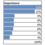
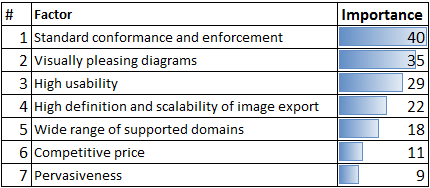
Clients ranked factors that a MBSE tool should satisfy from the most important to the least important and commented their choices. The most important factor received 10 points, the second received 9, etc. We calculated the percentage of the total score for each factor. A summary of scores is shown in Table 1.
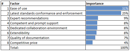
Table 1. Result of survey: Key factors that MBSE tools should satisfy
In addition to the key factors above, other factors were mentioned: large amount of documentation available, large user community, positive experience with other No Magic, Inc. products, multiplatform support (works on multiple OS), documentation template availability, and data interchange between documents and model.
Key Factors in Details
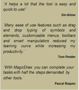
1. Ease of use
What is behind this factor?
Cameo Systems Modeler provides intuitive controls within a very well designed GUI, which allows users to model without having to spend time learning about the controls. Clients admire how quickly they can learn the GUI and they value the ability to save time and improve productivity. All major commands are available through as few clicks as possible.
This is identified as the first most important factor and competitive advantage.
Tim Weilkiens strongly emphasized the usability of a tool [1]. According to him, today, poor usability is one of the main hurdles of introducing a modeling culture in a company. Easy access to the most common operations is a cornerstone of MagicDraw’s user interface.
Cameo Systems Modeler is based on the award-winning MagicDraw modeling platform. The solution retains all the best diagramming, teamwork, persistence and documentation capabilities while offering more customized capabilities tailored to systems engineering needs.
No Magic also provides the first implementation of the SysML-Lite concept, described in A Practical Guide to SysML, 2nd Edition, by Sanford Friedenthal, Alan Moore, and Rick Steiner [2]:
“SysML-Lite is a simplified version of the language to help people get started modeling with SysML. It includes six of the nine SysML diagrams, and a small subset of the available language features for each diagram kind. SysML-Lite provides a significant modeling capability.”
Hundreds of usability features such as:
How is this achieved?
- We just listen!
- Each new release contains enhancements and fixes requested by our users and our internal team
- It is mature – 10 years in the market means a lot
- No Magic constantly researches and collaborates with many of the élite systems engineering experts to achieve simplicity and elegancy in solutions. No Magic spent about a year researching and collaborating with systems engineering experts, devising a way to simplify the transition from traditional to a Model-Based Systems Engineering approach which resulted in first implementation of the SysML-Lite concept
2. Latest standards conformance and enforcement
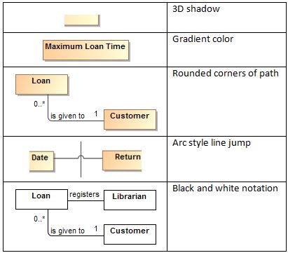
NoMagic’s MagicDraw provides the best support for diagrams of all of the tools I’ve ever used.
OMG SysML RFI Survey [3]
What is behind this factor?
The complete latest SysML 1.4 standard support. We were the first to implement V1.0, 1.1, 1.2, 1.3 and 1.4
Our clients and we, believe we have the most up-to-date and standards-compliant modeling solution in the industry.
- Cameo Systems Modeler supports the complete latest SysML 1.4 standard. We were the first to implement V1.0, 1.1, 1.2, 1.3 and 1.4
- Unlike most of the solutions in the industry MagicDraw does not use any tool-specific notations. Instead, Cameo Systems Modeler enforces diagram and model correctness based only onthe standards. Clients can be sure that their models are correct and fully standards complaint, so clients do not waste time correcting improper models
- The Cameo Simulation Toolkit provides the first in the industry extendable model execution framework based on OMG fUML and W3C SCXML standards
- The tool suite stores models in standard XMI format, which together with EMF XMI is also used for interchange
- The Requirements Interchange Format (ReqIF) support enables requirements import from requirements management tools, such as IBM DOORS 9.4 and 9.5, IBM DOORS Next Generation, PTC Integrity, Polarion, and Siemens Teamcenter
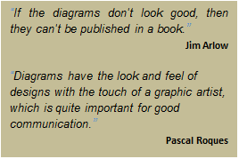
- Standards compliance is the most important factor found by book authors when preparing diagrams for a wide audience – as shown by a most reputable software and system engineering authors’ survey [1]
How is this achieved?
- No Magic is a top influential member in the Object Management Group (OMG) organization. Our experts are significantly involved in OMG standards development. We are typically standards compliant before the standards are released to the public. This is enabled by MagicDraw, a very versatile platform easily adaptable to changes in the standards
- No Magic is an official member of the OMG Model Interchange Working Group (MIWG) and UML Diagram Interchange (UMLDI) Group both formed to demonstrate and facilitate interoperability between modeling tools
- No Magic is an active member of INCOSE – International Council on Systems Engineering
3. Expert recommendations
MagicDraw will be the first choice.
OMG SysML RFI Survey [3]
What is behind this factor?
- World leading companies (including many from Fortune 500 and Global 500) use and recommend us for their partners
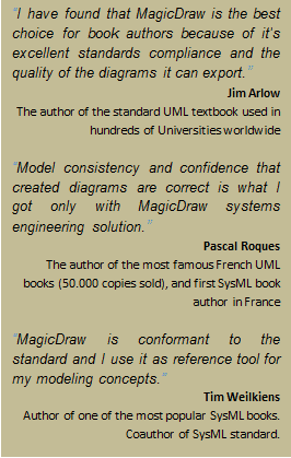
- The most reputable book authors use our products writing system engineering books [1]
- Due to high standard conformance and academic program availability, products are used in hundreds of universities training future experts around the world. One example is the French universities case [4]
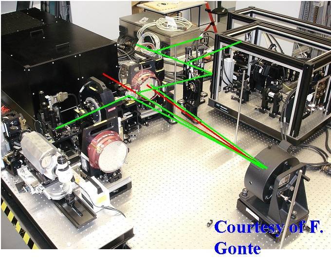
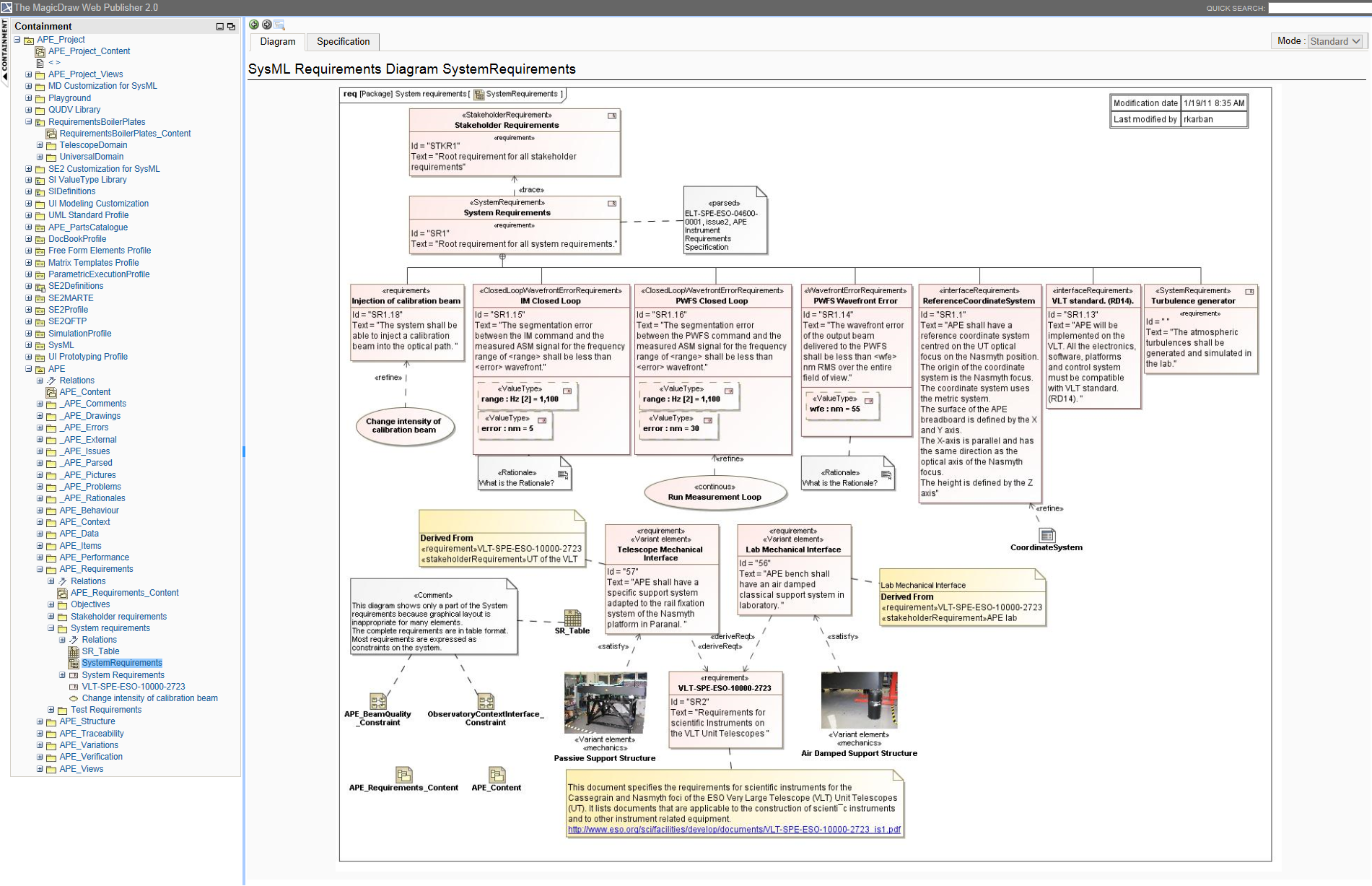
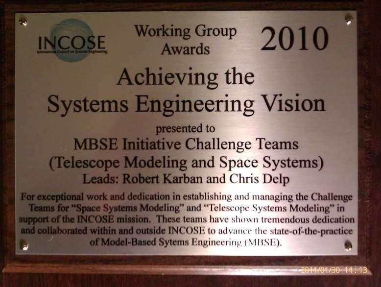
- Products are used by INCOSE MBSE Challenge Teams – pioneers for advance engineering solutions:

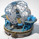
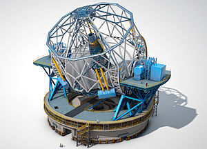
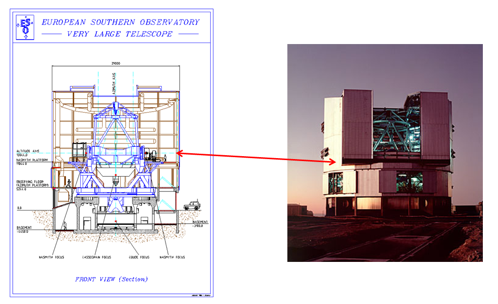
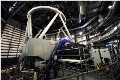
Figure 1. E-ELT- the largest optical telescope in the world compare the ESO’s Very Large Telescope and Statue of Libertyff
- MBSE Usability Team
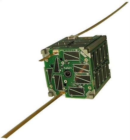
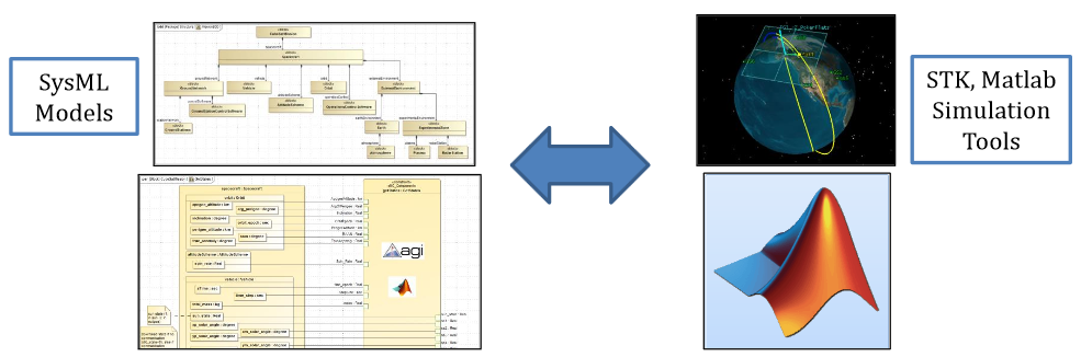
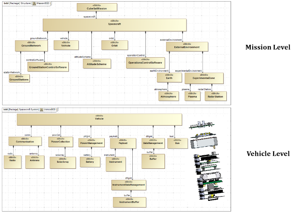
- Our products are used in top engineering projects: E-ELT[5], CubeSat [6] [7], US Navy Submarines [8], etc
- Top innovative organizations are using our products to move innovations into industry: NASA JPL, ESO, LMCO, Airbus, Kongsberg, BAE Systems, Raytheon, ABB Inc, Siemens AG, Hospira, NSN, BMW, GE, Raykiel, Konecranes Plc, Bombardier Transportation, Bernafon AG, KB Medical SA, Mechatronic AG, Sercel and others
- According to a comprehensive OMG SysML RFI survey [3] Magicdraw:
- Is second most post popular SysML tool – Figure 2
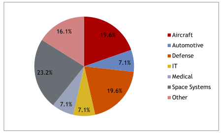
- Provides the best average value of all diagrams – Figure 3
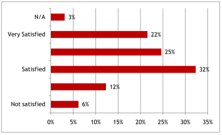
- Is the most satisfying SysML tool – Figure 4
-
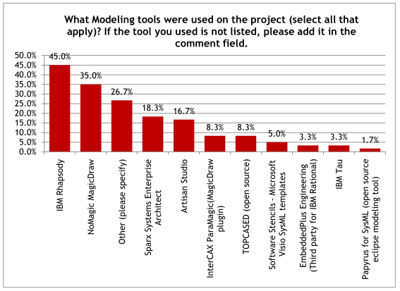
Figure 2. MagicDraw is second the most popular modeling tool
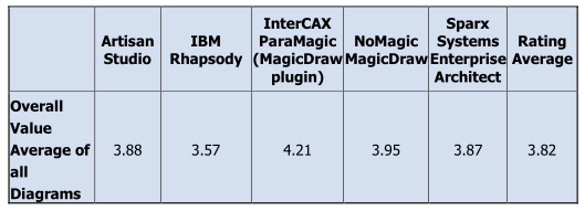
Figure 3. MagicDraw provides the best average value of all diagrams
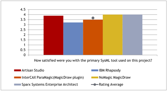
Figure 4. Systems engineers are most satisfied with MagicDraw
How is this achieved?
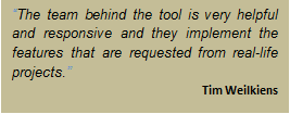
- Close collaboration with clients – most products capabilities were requested from our clients
- Partners program covering knowledge sharing with training, consultancy, and technology partners
- Stick to the standards, well extendable, usable, well covering all the factors listed in this survey.
- It’s extendibility is as best as possible as all the standards are implemented by extending the customization mechanism Domain Specific Language (DSL). This enables good products adaption in the organizations. That is why it is so well-liked and recommended by leading experts
- Self-promoting:
- One of the most popular UML / SysML tools in the market
- Available since 1998
- Over 500,000 installations in 90+ countries
- Used by top companies and educational institutions
4. Competent and prompt support
- All product and technology related technical questions are handled the same day, when possible
- The same experts, who create, analyze, and test products also provide customer support
- Instant chat available directly from www.nomagic.com gives immediate assistance, during US operational hours
- Self-help sources are available:
- Forum with thousands of posts is constantly monitored by No Magic
- Modeling blog dedicated for ideas, sharing and expanding modeling discipline
- Comprehensive documentation.
- Online videos
- Need more? Our consulting department with hundreds of hours experience is ready to assist with any model-based solution. We pride ourselves on working with every size company, both large and small, and tailoring our solutions to fit our customers’ needs
How is this achieved?
- Customer support is a direct link to the company experts developing the same products. Almost all of the development team dedicates up to 15% of time for customer support
- 3 centers (US, Europe, and Asia) around the world which can ensure almost non-stop 24/5 “follow the sun” support for first level issues and questions
- We invest a lot in the community by dedicating resources to actively supporting the forum and blog
5. Dedicated collaboration environment
- Collaboration server dedicated for corporate work on modeling projects
- All designs are stored in a single place, there are no longer files that are scattered around in the network; changes can be introduced in an orderly manner and without conflicts
- Collaborative environment enables: baselining, branching, merging, change tracking, configuration management, user permissions
How is this achieved?
- Environment capabilities are dedicated for model based projects:
- Granularity level is single element
- All capabilities are tuned to easy work with models
- Active work on new technologies and innovations. Our new scalable data-base repository will change the rules of the game on e-collaboration on enterprise level models (hundreds of thousands of elements, and hundreds of users, scalable, with flexible permissions schema)
6. Extendibility
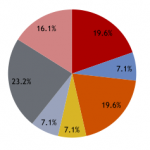
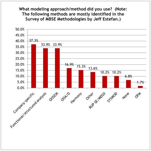
Extendibility is especially important when adapting tools for a required modeling method. As the report [3] shows (Figure 5) most projects and organizations use company specific approaches which require high flexibility, and extendibility from the tool, but on other hand, also high standard conformance.
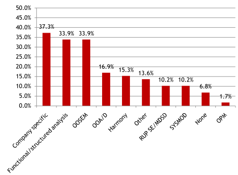
Figure 5. Modeling approach, method used in system engineering projects
How is this achieved?
DSL. The Domain Specific Language Customization Engine allows adapting the tool to the domain specific profile, or modeling domain. You can adjust and extend the product covering most of your needs without any coding. A lot of capabilities including: model-based metrics, custom diagrams, and smart packages gives you code free customization freedom
- Object Constraint Language (OCL). OCL expressions can be added to any model element. Executable constraint checks the model for correctness and completeness, displays errors in the model and suggests solutions.
- Open API
- Scripting Engine – scripts in BeanShell, JRuby, Jython, Groovy and JavaScript to create custom action for repetitive tasks
- Report Wizard with the customizable WYSIWYG reports supporting any style of documentation
- Last but not least, we assist our clients in creating custom solutions including Open API support
This means that the product can be fully adapted to ANY client’s organization needs, and to the needs of multiple internal organizations.
How is this achieved?
We are typically standards compliant even before the standards are released to the public. In order to enable this we required MagicDraw to become a very versatile platform that is easily adaptable to changes in the standards. MagicDraw extendibility is the best as possible as all the standards are implemented by extending it’s customization mechanism DSL.
7. Quality of documentation
- High quality documentation covers all parts of the product including: manuals, online demos, and help
- Major capabilities are documented with a few real world use cases from our customer’s experience
How is this achieved?
- Dedicated team of technical writers participates in each capability creation from the beginning
- Product managers, consultants and analysts provide real world use case and review each part of the documentation
8. Competitive price
We leverage between expensive, often stagnant, inflexible, old fashioned solutions and inexpensive, well-known, but in many aspects, fragile products which just scratch the systems engineering surface. We maintain a strong reputation for the product with the best price for value.
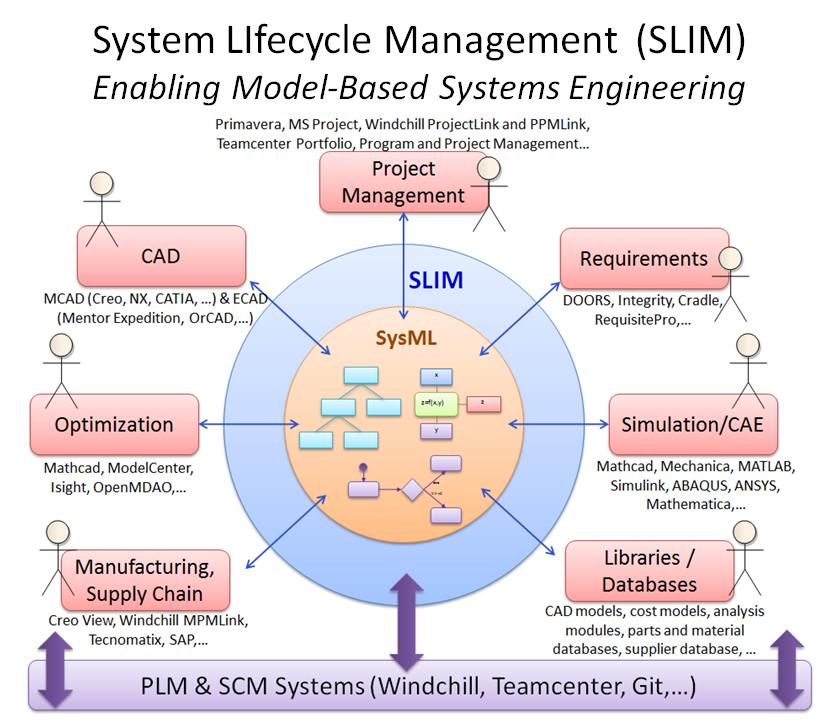
About MBSE solution
No Magic’s Model-based Systems Engineering Solution is the most standard compliant application of modeling to support: System Requirements, Analysis and Simulation, Design, Verification and Validation.
Our product speaks the common language – Systems Modeling Language (SysML 1.4) which is understood across a significant proportion of the systems engineering community.
Flagship products:
- The Cameo Systems Modeler is Model-Based Systems Engineering (MBSE) software enabling single users or an entire engineering team to create, collaborate, and manage systems requirements and designs. It’s the most up-to-date and standards-compliant modeling solution in the industry. The complete SysML 1.4 standard implementation is wrapped into an intuitive user interface for a simplified modeling experience
- The Cameo Simulation Toolkit provides the first in the industry extendable model execution framework based on OMG fUML and W3C SCXML standards. It extends the UPDM plugin to validate system behavior by executing, animating, and debugging SysML Parametric models in the context of realistic mock-ups of the intended user interface
Flagship products come with multiple extensions and integrations.
Our solution enhances the ability to capture, analyze, share and manage the information associated with the complete specification of a product, resulting in the following benefits: improve communication, increased ability to manage system complexity, improved product quality, enhanced knowledge capture and reuse, and improved ability to teach and learn systems.
Further Steps
We are happy to provide products that are so widely and so well recognized. From the interview and survey we also received a list of very valuable requested improvements. This will help us to continue to deliver the highest standard of solutions in the future.
References
[1] Pavalkis, Saulius. Why Modeling Book Authors Use MagicDraw As Their Primary Selection. Modeling Community Blog, 2014. Available at http://blog.nomagic.com/why-modeling-book-authors-use-magicdraw-as-the-best-product/
[2] Friedenthal, Sanford, Alan Moore, and Rick Steiner. A practical guide to SysML: the systems modeling language. Elsevier, 2011.
[3] Cloutier, Robert and Bone, Mary. Compilation of SysML RFI- Final Report, Systems Modeling Language (SysML) Request for Information OMG Document: syseng/2009-06-01, February 20, 2010. Available at http://www.omgwiki.org/MBSE/lib/exe/fetch.php?media=mbse:omg_rfi_final_report_02_20_2010-1.pdf
[4] Pavalkis, Saulius. MBSE Courses and Book, Prepared and Adopted by French Academic Institutions. Modeling Community Blog, 2014. Available at http://blog.nomagic.com/mbse-courses-and-book-prepared-and-adopted-by-french-academic-institutions/
[5] Pavalkis, Saulius. MBSE in Telescope Modeling: European Extremely Large Telescope – World’s biggest eye on the sky. Modeling Community Blog, 2014. Available at http://blog.nomagic.com/mbse-in-telescope-modeling-european-extremely-large-telescope-worlds-biggest-eye-on-the-sky/
[6] Spangelo, Sara C., et al. Applying model based systems engineering (MBSE) to a standard CubeSat. Aerospace Conference, 2012 IEEE. IEEE, 2012. Available at http://www.omgsysml.org/mbse_cubesat_v1-2012_ieee_aero_confr.pdf
[7] Spangelo, Sara C., et al. Model based systems engineering (MBSE) applied to Radio Aurora Explorer (RAX) CubeSat mission operational scenarios. Aerospace Conference, 2013 IEEE. IEEE, 2013. Available at http://www.agi.com/downloads/resources/white-papers/mbse-cubesat-2013-%20ieee-%20aero-%20conf.pdf
[8] Pavalkis, Saulius. Model Based Management of Configurations of Complex Systems: Common Submarine Combat System. Modeling Community Blog, 2014. Available at http://blog.nomagic.com/model-based-management-of-configurations-of-complex-systems-common-submarine-combat-system/
Image source: ESO, Bombardier

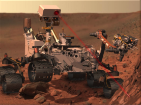 JPL NASA is successfully applying MBSE to real project systems engineering problems across a wide landscape of project types, activities and lifecycle phases. Approximately 20 development tasks are applying MBSE at JPL across the full lifecycle. JPL’s Mission for NASA is Robotics space exploration in following areas: Mars, Solar system, Exoplanets, Astrophysics, Earth Science, and Interplanetary network. MBSE is used in the following missions: