SysML allow both structural and behavioral modeling of the system. SysML models can be formally interpreted and executed. Ones executed analysis can be performed at system level. Ones we are good with simulation results we can prototype. Using programmable Lego Mindstors NXT for prototyping is an out of the box way to test and demonstrate future system behavior. We can use same system model to control and calibrate prototype.
In the first article from the series of two we will create automatic transmission system model in SysML, describe transmission controller behavior, analytical model, user interface, and execute the model.
See video demonstrating final model:
Final project file: Transmission.mdzip
In the second part we will connect SysML Transmission Model to Lego Mindstorms NXT gearbox. Model will control switching between gears.
Motivation behind Model Execution
The purpose of a simulation is to gain system understanding without manipulating the real system, either because it is not yet defined or available, or because it cannot be exercised directly due to cost, time, resources or risk constraints. Simulation is typically performed on a model of the system.
Executable modeling allows system simulation and enables following engineering analysis:
- Evaluate design alternatives
- Select the best set of parameters
- Verify system constraints
- Perform requirement compliance analysis
- Perform what-if analysis
- Execute SysML and UTP test cases
“This is an important development since it requires minimal configuration, can be used earlier in the lifecycle and can evolve as the design matures.”
NASA Perspective on Recent Trends in Executable Models
“Executable UML is the next logical, and perhaps inevitable, evolutionary step in the ever-rising level of abstraction at which programmers express software solutions. Rather than elaborate an analysis product into a design product and then write code, application developers of the future will use tools to translate abstract application constructs into executable entities. Someday soon, the idea of writing an application in Java or C++ will seem as absurd as writing an application in assembler does today.”
Grady Booch
Transmission System
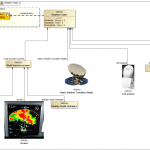
Modern transmission consist not only from mechanical parts but also from electronics. Transmission control unit (Figure 1) controls gearbox and switch between gears based on many car parameters.
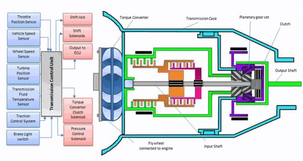
Figure 1. Transmission System
Structure of the Model
To describe transmission controller and demonstrate how gears in the gearbox are changed we will create:
- Structure diagrams – describes parts of the transmission and interfaces
- Behavior diagrams – describes behavior of the transmission
- Parametric Diagram – describes analytical part of the model.
We will combine all the diagrams to have one system behavior description. We will add UI and will execute model. We will setup automatic requirements verification.
Behavior of the Transmission
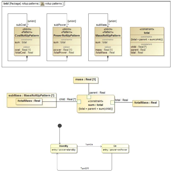
For behavior part of the transmission we will use State Machine diagram. State machine describes possible states of a particular block and transitions between states. In Figure 2 we see simple state machine which can be executed by its own without context – structural part of the system.
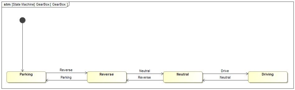
Figure 2. State Machine
If we want update value properties depending on state, for example active gear (Figure 3), we need context which will hold those properties.
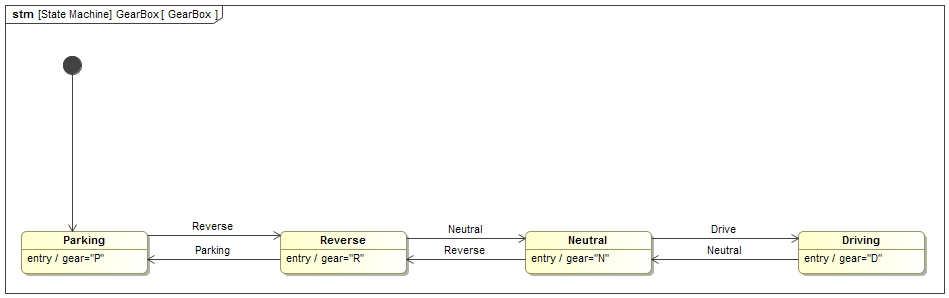
Figure 3. State Machine with entry action to update property value
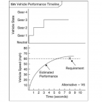
Final State machine diagram (Figure 4) depending on gear: changes differential gear ratio (1), increases RPM (2), on RPM change switches gears (3).
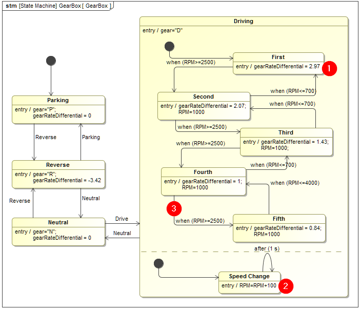
Figure 4. Final State Machine
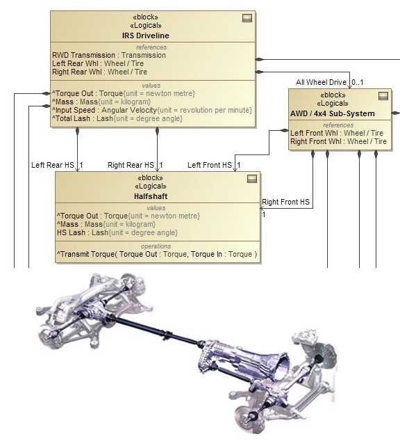
Structure of the Transmission
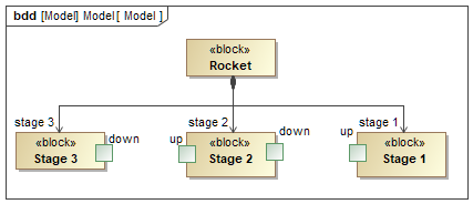
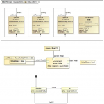
We will describe structure of the transmission with block definition diagram (BDD) (Figure 5). BDD is used to define blocks in terms of their features and structural relationships with other blocks. In SysML, systems are built from basic structural elements called blocks. Blocks include features that allow us to describe same real-world attributes in a system model.

Figure 5. Transmission system structure
Note that state machine is owned by block which behavior it’s represents (Figure 6).
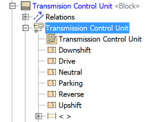
Figure 6. State machine shall be in the context of the system which behavior it describes
Project Structure is important. Behavior descriptions need to be contained underneath the element which is executed. Executable element can only have one main behavior. Recommendation for the main behavior which controls other behaviors is to use State Machine Diagram. State Machine diagram can be enriched with other behaviors e.g. start activity on enter to state, or execute code as effect of switch between states.
Vehicle Speed Analysis
We defined behavior description and connected to structure. Now we want to enrich model with more parameters and want to do additional static and dynamic calculations. For these tasks we need to create parametric diagrams.
Parametric diagram connects SysML Constraint blocks as a network of reusable constraints that represent mathematical expressions, which constrain the physical properties of a system. SysML parametric diagrams provide a way to integrate engineering analysis models described in mathematical equations and constraints, with design models describing the structural and behavioral aspects of systems.
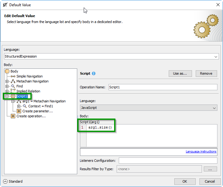
Our goal will be to calculate vehicle speed from engine Revolutions per Minute (RPM). We will use following four (Figure 7) mathematical expressions. We will formalize them in SysML constraint blocks.
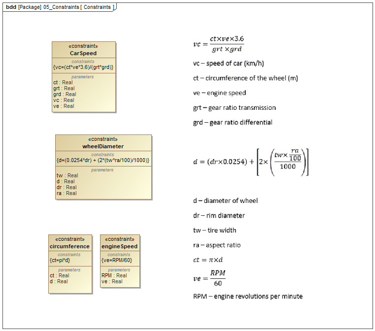
Figure 7. Expressions formalization with constraint blocks
As an input we will need wheel characteristics (Figure 8).
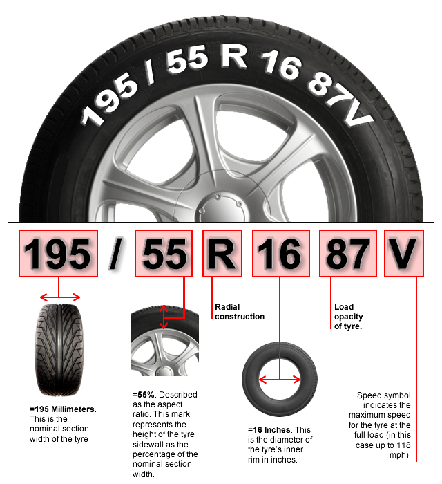
Figure 8. Wheel characteristics required for vehicle speed calculation
We will create value properties in Transmission Control Unit to hold inputs, intermediate, and result values of analysis (Figure 9).
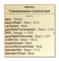
Figure 9. Transmission Control Unit with value properties
Now in Transmission Control Unit we will create SysML parametric diagram to connect constraints with value properties (Figure 10).
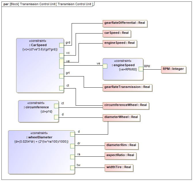
Figure 10. Parametric diagram to calculate vehicle speed based on RPM
We will execute parametric model to get results based on the inputs. Execution of mathematical models expressed as SysML parametric diagrams enables automatic dependent parameter value updates at any time during simulation. Mathematical expressions can be solved using build-inn math engine or well-known math solvers.
Figure 11 shows (1) parametric diagram execution button, (2) Simulation dialog variables tab with executed model and instantly calculated values.
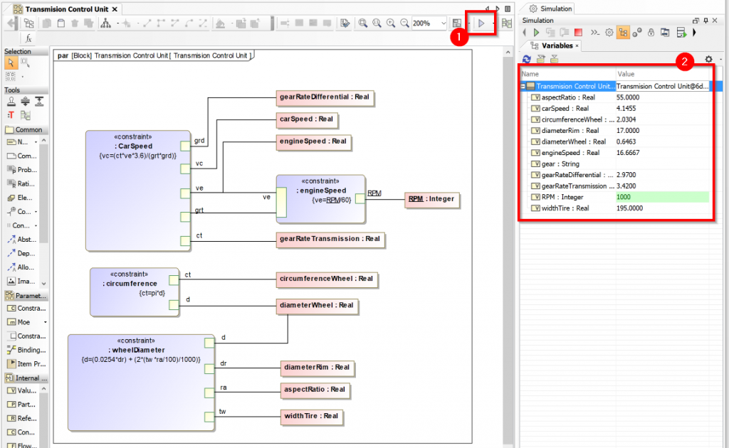
Figure 11. Parametric diagram execution
User Interfaces Mockups
User interface model can be created using User Interface Modeling Diagram. Using drag’n’drop it connects various system parts to GUI components.
- Classes/Blocks to Frames
- Signals to Buttons
- Properties to Labels
- Images to active element switchers
In User Interface Diagram (Figure 12) we will define mockups (blue color lines) and connect to system model (red color lines).

Figure 12. User Interface mockup
Additionally:
- Web based UI – enable to run simulation remotely.
- Open API allows using dedicated third-party tools of choice to create and plug realistic system mockup;
Simulation Configuration
To have user interface mockups in the model we will create simulation configuration diagram (Figure 13). In simulation configuration diagram simulation configuration element (2) define what elements needs to be executed, what UI used, and all execution related properties. One’s configuration is created it appears and can be started from dropdown Executions List (1). To have gear handle switching animation we will use Image Switcher (3) which allows animation by using multiple images representing different system states.

Figure 13. Model execution configuration diagram
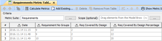
Requirements Verification
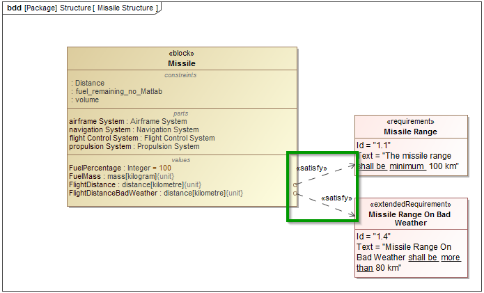
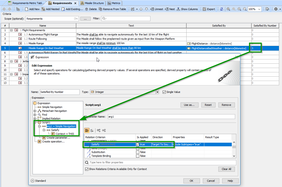
For automatic requirements verification we will create satisfy relation from Transmission Control Unit block property RPM to requirement which it shall satisfy (Figure 14). With help of model execution and analysis we will check is value of this property (and design) satisfy requirement or not.
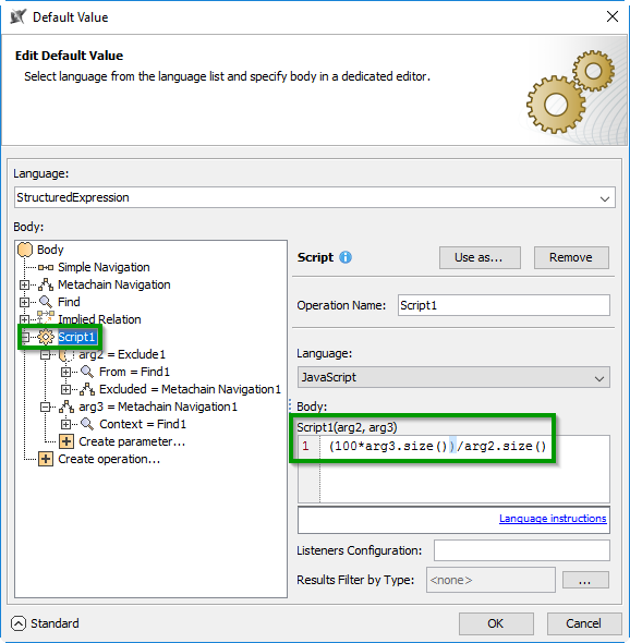
But what is success criteria? How to formalize text based requirement to constraint block value property? For this purpose we create constraint block which refines requirement. So property which satisfies requirement is constrained by constraint block constraint which refines requirement (Figure 14).
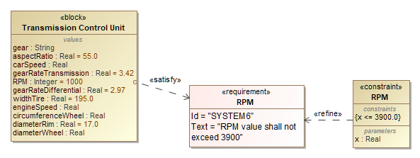
Figure 14. System characteristics and requirement relation
Note that in simple cases manual requirement refinement with constraint block is not required. Natural language analysis capability available in modern modeling tools recognize text pattern based one predefined and customizable ones and create constraint automatically [1].
Simulation of Coordinated Entities
Simulation Configuration
Is used to define what elements needs to be executed, what UI used, and all execution related properties, charts, results and input location.
Structure and Behavior
Project Structure is important. Behavior descriptions need to be contained underneath the element which is executed. Executable element can only have one main behavior. Main behavior is defined with property “Classifier Behavior”. Recommendation for the main behavior to use State Machine Diagram. State Machine diagram as a governing diagram
State Machine and Other Behavior Diagrams e.g. Activity Relation
As OMG fUML execution model is used as foundation for all kinds of executions, but does not support statemachines, SCXML engine is wrapped to fUML Execution interface to fill this gap and provide complete integrated execution of different UML behaviors. It allows calling Statemachine in CallBehaviorActions, use Activities to define entry/do/exit activities of the State, use SendSignalAction to trigger Transitions in the Statemachines.
Parametric Diagrams
It should be contained in the structural element which needs to be executed.
Reusable Elements
Reusable elements (Interface Blocks, behaviors (if not the main behavior) signals, Constraint Blocks, etc.) can be contained anywhere in the model.
Communication of Subsystems
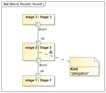
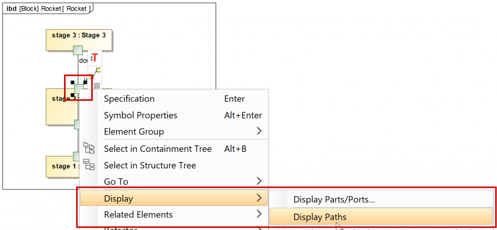
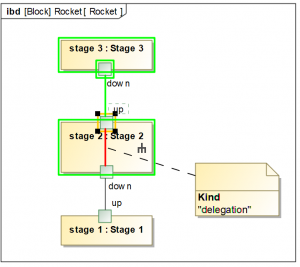
There are situations where you want to describe how two independent subsystems communicate with each other. Signals send by one block behavior can control another block behavior e.g. trigger sate transition (Figure 15). This task can be performed in the tool but requires to have:
- Description how these subsystems communicate (IBD);
- Through which port signal should be sent
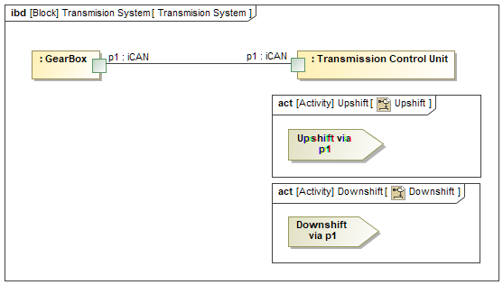
Figure 15. Ports and send signal actions relation
Activities which are used to send signals can be connected to state machine diagram and invoked during execution as effect on transition or as behaviors performed on Entry/do/exit from state (Figure 16).
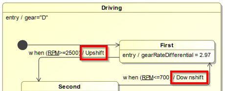
Figure 16. Part of state machine which user’s activities as effect on transmission to send signal
Instead of simple RPM we could have probability based RPM described in activity diagram (Figure 18).
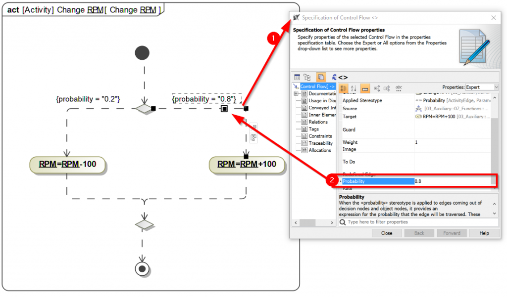
Figure 18. Activity diagram describing RPM change logic
Running model execution
One’s transmission model is created it can be executed (Figure 17) (1). On execution Simulation window will open (2). It contains four tabs: Sessions, Console, Variables, and Breakpoints. At this point, an instance of the Transmission Control Unit is created, which you can see in the Variables tab. In addition, a simulation session to execute the Transmission Control Unit block is created, which you can see in the Sessions tab of the Simulation window. The classifier behavior (state machine) of the Transmission Control Unit block, starts executing (3). A new session to execute the state machine is created under the simulation session of the Transmission Control Unit (2), and the Transmission Control Unit state machine diagram is open and started from the initial Pseudostate and automatically move to the Parking state because the Transition that connects between the initial Pseudostate to the Parking State does not have a defined trigger. When the ready State is entered, its entry Behavior is executed, which executes property update gear=”P”.
At the same time parametric diagram is evaluated, it takes default values and calculates results based on expressions. On any value change parametric diagram is recalculated. RPM value is marked green or red depending on connected requirement (Figure 14) which it satisfies or not.
Last user interface mockup and gear switch animation is displayed (4).
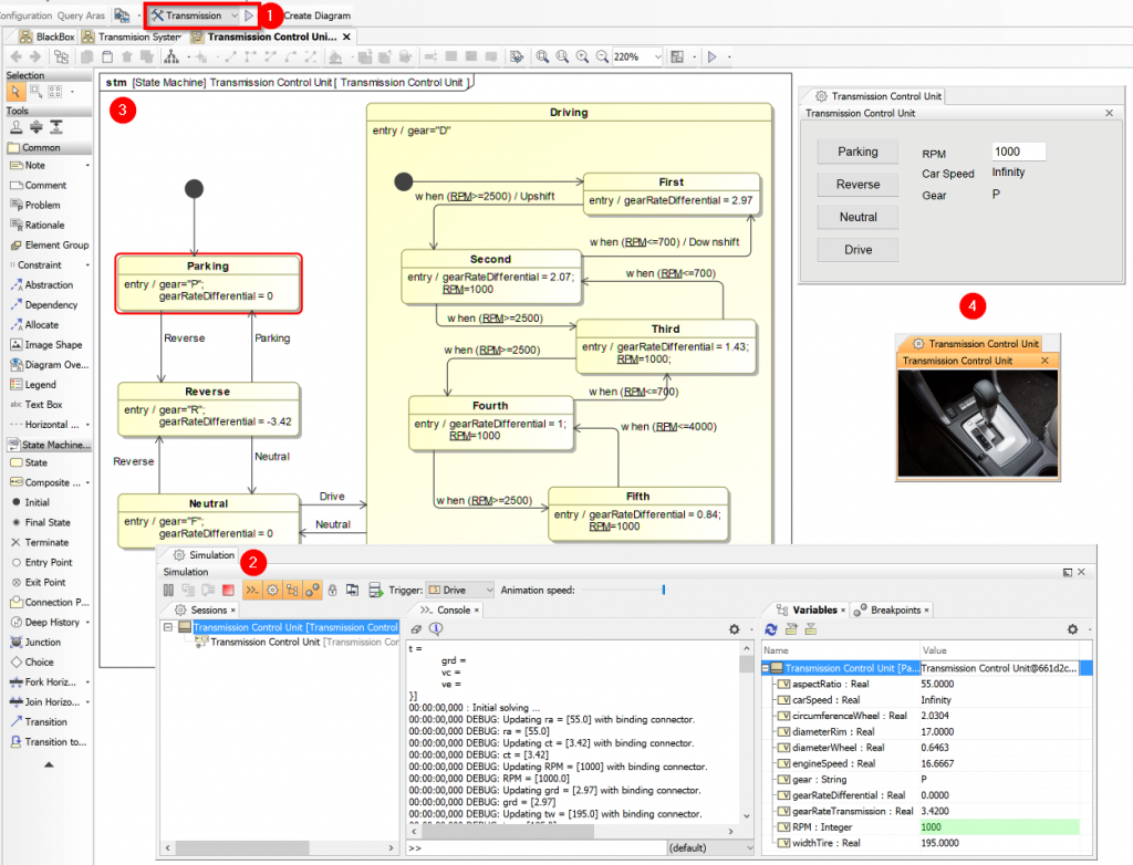
Figure 17. Transmission Control Unit system execution
Challenge
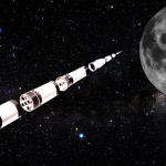
Perform analysis to find the best switching between gears or gears rate differential and optimize transmission system for fastest acceleration (Figure 19). For this save execution results into instance or file and compare between different configurations.

Figure 19. Transmission optimization to provide more power on exploration. Source: https://www.youtube.com/watch?v=36H9BVeMYMI
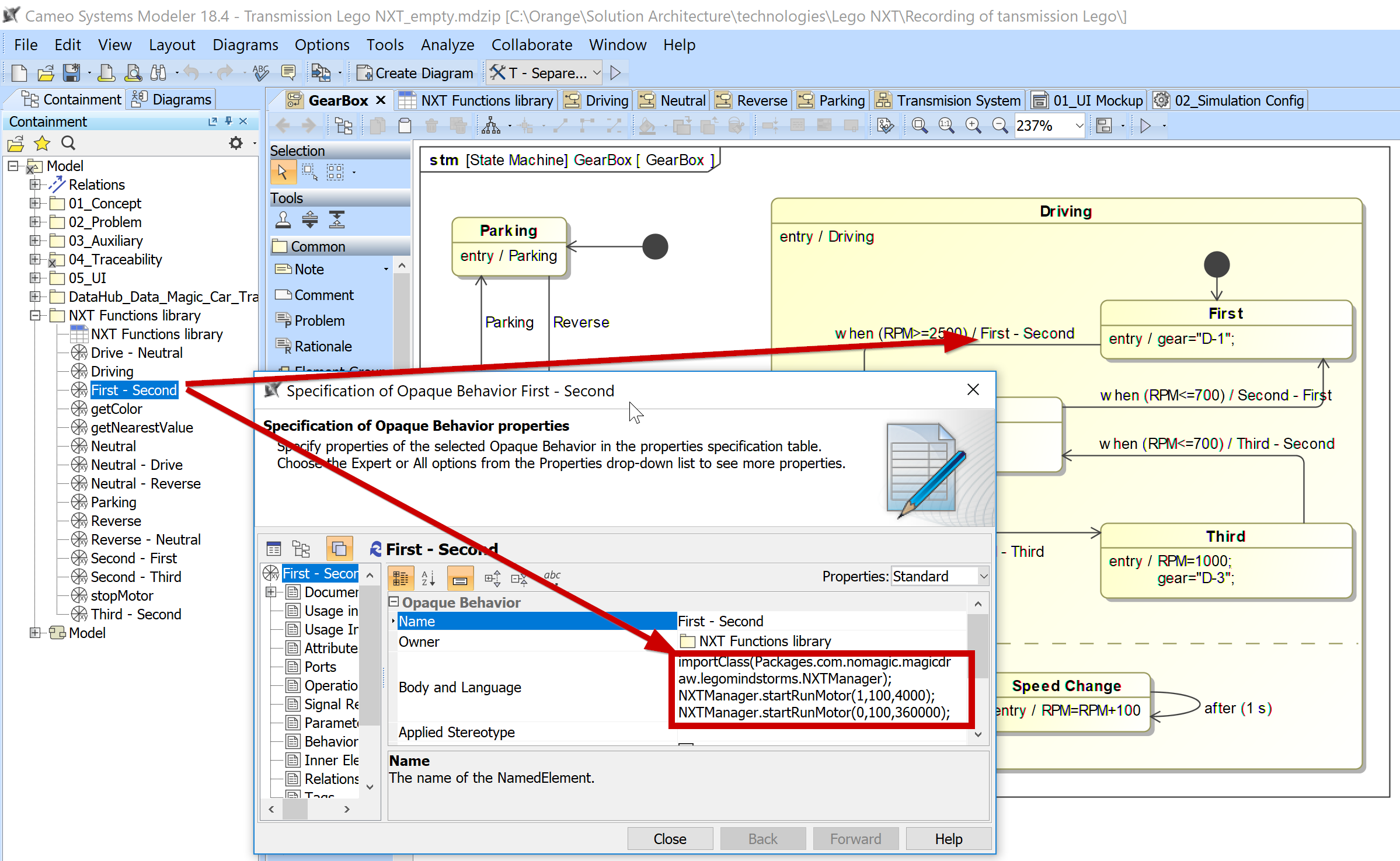
SysML Transmission Model Controlling Lego Mindstorms NXT Liner Gearbox
In the second part of the article from the series we will connect SysML Transmission Model to Lego Mindstorms NXT liner gearbox (Figure 20). Model will control switch between gears.
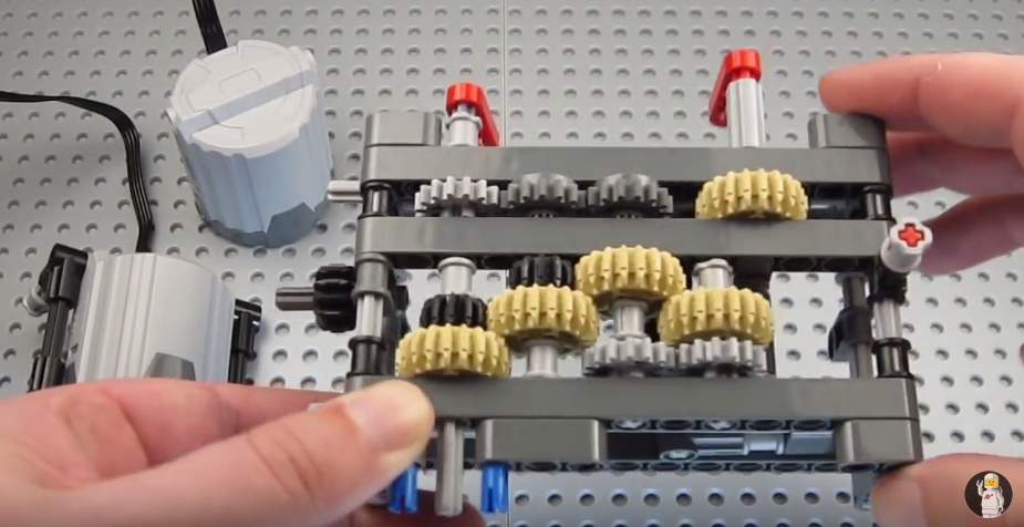
Figure 20. Lego 4 gears linear transmission model used to prototype. Source: https://www.youtube.com/watch?v=0Aw23jQkP2g
For more about Cameo Simulation Toolkit and Lego Mindstorms NXT integration refer to [2].
References
- https://docs.nomagic.com/display/CRMP185/Extracting+Constraint+from+Requirement
- https://blog.nomagic.com/collaboration-between-simulated-model-and-external-system-controlling-lego-mindstorms-with-cameo-simulation-toolkit/
Download
About Cameo Simulation Toolkit
The Cameo Simulation Toolkit provides the first in the industry extendable model execution framework and infrastructure based on number of standards:
- Model debugging and animation environment
- Pluggable engines, languages and evaluators
- User Interface prototyping support
- Model driven configurations and test cases
The standard based model execution of:
- Activities (OMG fUML standard)
- Composite structures (OMG PSCS)
- State Machines (W3C SCXML standard)
- Actions/scripts (JSR223 standard)
- Parametrics (OMG SysML standard) including build in and external math solvers: Math solvers: Built-in solver, Matlab, Maple, Mathematica, OpenModelica.
- Sequence diagrams (OMG UML Testing Profile)
Authors: Zilvinas Strolia and Saulius Pavalkis
Zilvinas is a Solution Architect at No Magic Europe. His expertise area is model-based systems engineering (MBSE) with special focus on model execution.
Zilvinas has an engineering degree from Kaunas University of Technology (Lithuania) and almost 10 years of work experience in this field. He also holds the OMG-Certified Systems Modeling Professional (OCSMP) certificate.
Zilvinas is responsible for consulting and delivering the solutions to customers. He occasionally writes papers and produces training material (slides, samples, practical assignments).
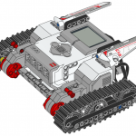
 This blog post covers the integration process of the latest versions of Lego Mindstorms EV3 and Cameo Systems Modeler. Next post will cover actual modeling and simulation Lego EV3 in SysML. Flow instructions and video below!
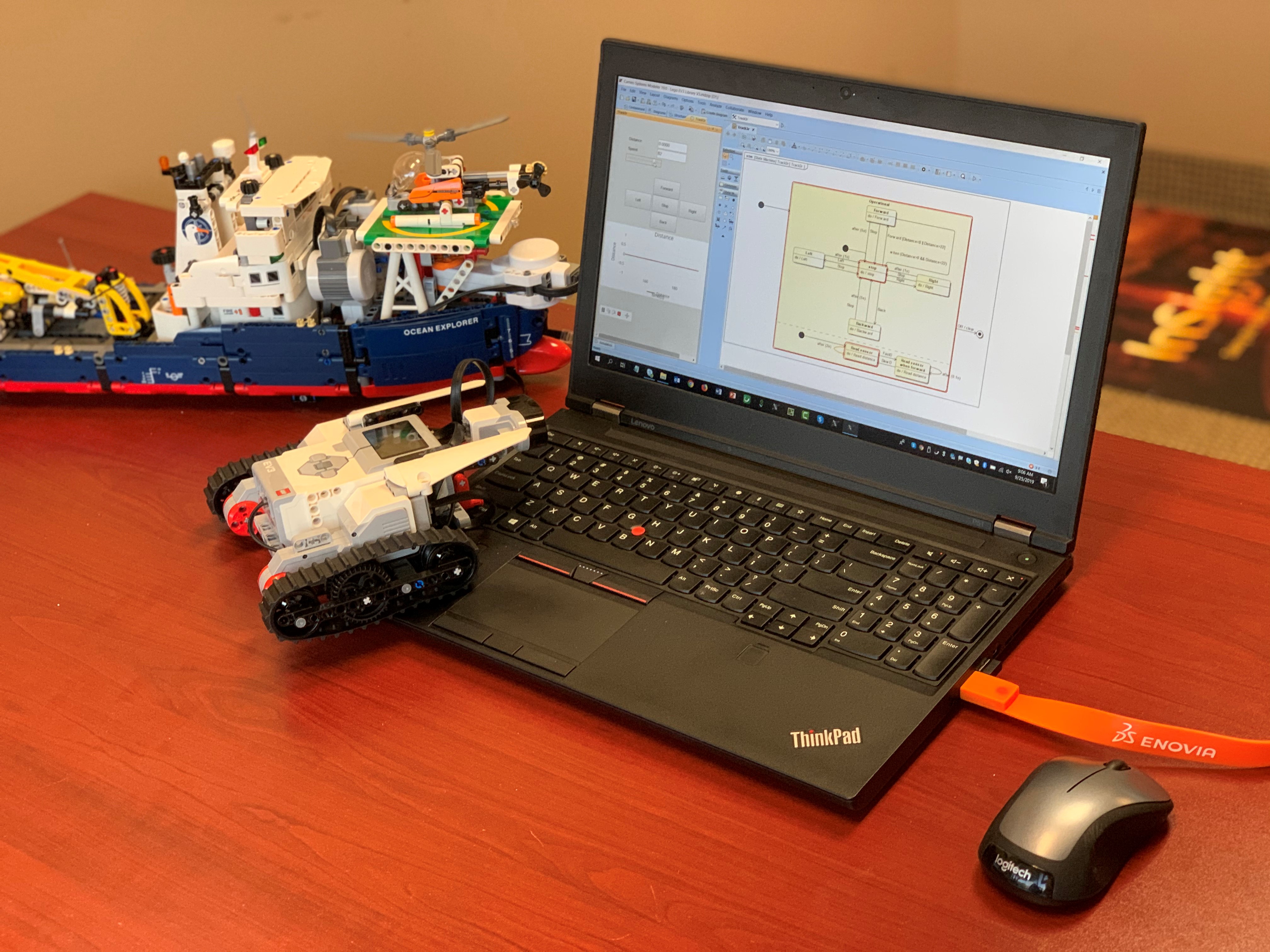

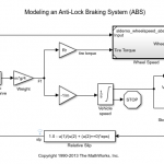
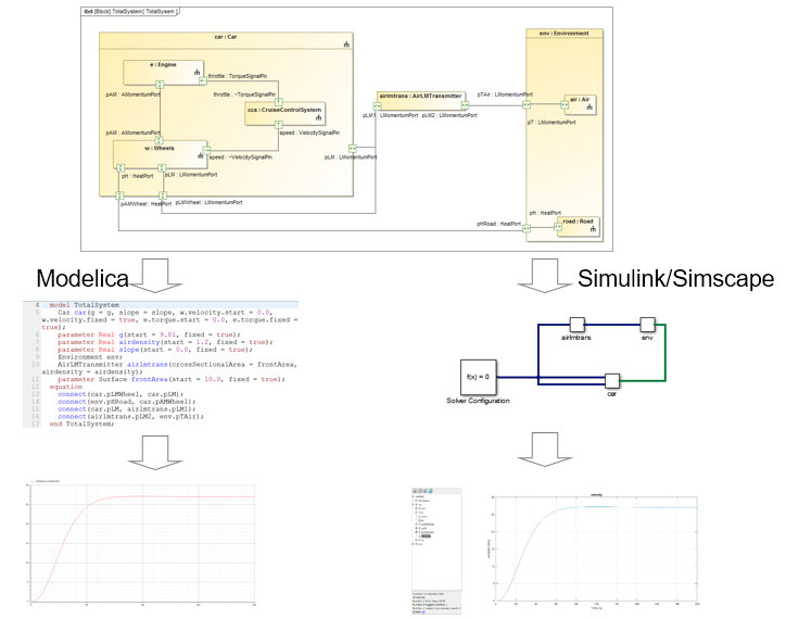
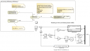 We often get question how Cameo Systems Modeler (or MagicDraw) and SysML/UML integrates with MATLAB/Simulink? Let’s go through integration use case and current implementations.
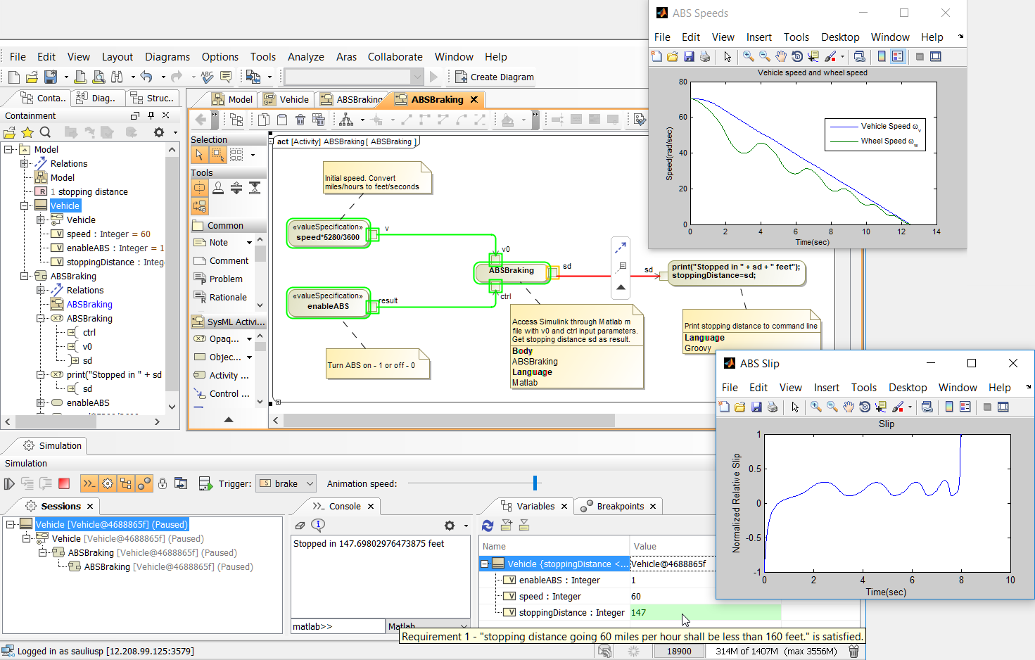

 We would like to share a list of generic No Magic’s recommendations for the best practices on model management in Cameo tools suite. How should the model be broken up to optimize from the project architecture perspective and element reuse?


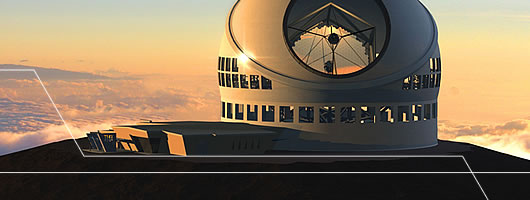 The Thirty Meter Telescope (TMT) system is currently being developed by the TMT Observatory Corporation. The main objective for the TMT related analysis is to provide state-dependent power roll-ups for different operational scenarios and demonstrate that requirements are satisfied by the design as well as mass roll-ups and duration analysis of the operational use cases.