 The research was carried out at the Jet Propulsion Laboratory (NASA JPL) under a contract with the National Aeronautics and Space Administration and the European Southern Observatory (ESO).
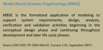
The work presented in this paper describes an approach used to develop SysML modeling patterns to express the behavior of fault protection, test the model’s logic by performing fault injection simulations, and verify the fault protection system’s logical design via model checking. A representative example, using a subset of the fault protection design for the Soil Moisture Active-Passive (SMAP) system, was modeled with SysML State Machines and JavaScript as Action Language. The SysML model captures interactions between relevant system components and system behavior abstractions (mode managers, error monitors, fault protection engine, and devices/switches). Development of a method to implement verifiable and lightweight executable fault protection models enables future missions to have access to larger fault test domains and verifiable design patterns. A tool-chain to transform the SysML model to jpf-statechart compliant Java code and then verify the generated code via model checking was established. Conclusions and lessons learned from this work are also described, as well as potential avenues for further research and development.
INTRODUCTION
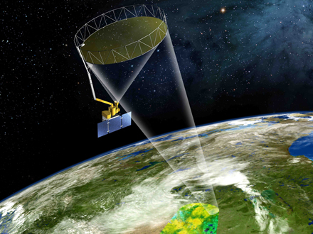
The Soil Moisture Active Passive (SMAP) mission will provide global measurements of soil moisture and its freeze/thaw state. These measurements will be used to enhance understanding of processes that link the water, energy and carbon cycles, and to extend the capabilities of weather and climate prediction models. SMAP data will also be used to quantify net carbon flux in boreal landscapes and to develop improved flood prediction and drought monitoring capabilities [6].
Highly complex systems, such as the SMAP Fault Protection system [1], are difficult to develop, test, and validate using traditional methods – Fault protection design has been prone to human error and subject to limited multi-fault, multi-response testing. Traditionally, responses are designed individually because it is not feasible for humans to incorporate all combinations of fault protection events in design or test without a model. It is also expensive to use high fidelity test beds, limiting the scope of the possible combined-response tests that can be performed. To explore new model-based methods of testing and validating fault protection, SMAP Fault Protection logical designs were used to architect a representative SysML behavioral model that was used to exploit fault injection testing and model checking capabilities. Model checking provided a basis for checking fault protection design against the defined failure space and enabled validation of the logical design against domain specific constraints (for example, during ascent the receiver should be on and the transmitter should be off).
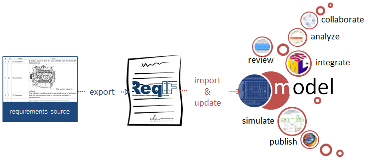
The model is transformed to run simulations, create artifacts to be model checked, and to produce the final software implementation.
In order to gain confidence in the validation and verification of the model based design and its implementation the following questions must be addressed:
In the context of this paper, simulation is used to validate the model against requirements. It is also assumed that the generated artifacts for model checking represent the model. However, this could be mitigated by comparing the simulation results with the execution of the generated code for model checking. Finally, the code used for model checking is not part of the final software system implementation. Simulation of the model caught (initial modeling and design translation) errors and provided the ability to inject a variety of inputs to test many aspects of the model, leading to confidence in the logical design of the model. It became clear, as more error monitors and responses were added to the model, that it would not be possible to manually run simulations for all of the possible sequences of the model – a model checker is necessary to formally and exhaustively verify the model for all possible sequences.
TOOLCHAIN
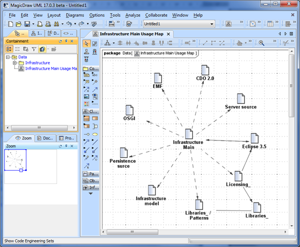
The tool-chain consists of: a UML modeling tool (MagicDraw 17.0.4) with SysML plugin and simulation environment (Cameo Simulation Toolkit 17.0.4 which is based on Apache SCXML Engine 0.9), a model-to-text transformation tool (COMODO), and a model checker (JPF6 and JPF7).
MagicDraw is used to model and represent the system in terms of collaborating Statecharts according to SysML 1.3. The model is exported in UML2 XMI 2.x format and then processed by COMODO.
COMODO [3] is a platform independent tool to generate text artifacts from SysML/UML models using Xpand/Xtend technology. For example COMODO can transform SysML State Machine models to Java code which is compliant with JPF’s Statechart project (jpf-statechart) and the final software implementation for different platforms.
Statecharts XML (SCXML) is a W3C notation for control abstraction defining the syntax and semantic for Statecharts execution [5]. Apache Commons SCXML is one implementation of SCXML.
MODELING FOR MODEL CHECKERS
An idea of the overall complexity of the SMAP model is provided in the following figure. The SMAP Fault Protection Engine consists of an Error Monitor Statechart and Response Statecharts. External signals from device Statecharts, such as a reaction wheel, and the mode manager Statechart are input to the Fault Protection Engine.
The size of the model checking state space is a valuable indicator for the complexity of the model. Model checkers are computation and memory intensive. After initial model checking runs were found to take days to exhaustively check a small subset of the SMAP Fault Protection system, it became apparent that model patterns should aim at decreasing the state space. In an attempt to reduce the state space, adjustments were made to the model architecture and the Statechart representation of the fault protection system’s response tiers and response queue.
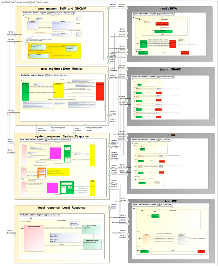
Figure 1: SMAP model.
Response tiers define the sequence of actions performed by fault protection system responses. Each subsequent tier of a given response attempts to mitigate a fault with different sets of actions. If a response has more than one tier, subsequent tiers will not be performed until prior tiers fail to mitigate the fault. The error monitor that detects the fault must be re-tripped between each subsequent tier. In cases where all tiers are executed and the fault still exists, the response resets and re-executes its tiers (assuming the response has not been masked).
When system responses are tripped by error monitors, they are placed in the fault protection response queue based on priority: High priority responses are placed in the front and low priority responses are placed in the back. A set of activation rules evaluates the response in the front of the queue and either allows the response begin executing its tiers or, if the activation rules do not pass, denies response execution and places the response back into the queue.
The Statechart in Figure 2 with orthogonal regions provides a straightforward example of a model checking application. The correctness property inserted is to ensure that state B and state E are never active at the same time: assert (inState(B) && !inState(D)).
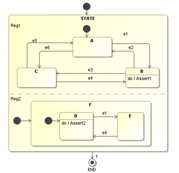
Figure 2: JPF Model Checking Example.
This Statechart is translated to Java using COMODO and the correctness property has been inserted manually into the code as shown in.
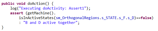
Figure 3: Inserting the Correctness Property.
When JPF was run, it instantly found a counterexample to the assertion and output the error trace and performance statistics shown in the following figure. Following trace #1, error #1 was found because trace #1 defines an existing path that leads to B and E being active together. The statistics show that there is no elapsed time needed to perform this very basic model-checking task.
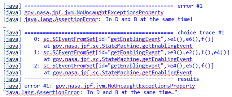
Figure 4: JPF Output of Error Trace.
The adjustments made to the SMAP model in order to reduce the state space include: 1) Use of composite Statecharts with orthogonal regions to define each behavior. It was verified that the state space of a Statechart with orthogonal regions is equivalent to a flat state machine since Statecharts are only a notational enhancement of the state machines. However the Statechart representation is more compact and the model is more readable; 2) Guards were placed on transitions wherever possible. The difference in computation time for a model with few guards compared with another model of triple size with many guards was found to be a factor of 5000 (see Table 2). Adding guards to most transitions reduces the complexity of the system to be checked, limiting the number of paths making it quicker to check; 3) The usage of enumeration instead of integer reduced the risks of state space explosion due to unbound variables. In the example of Figure 5 the model checker will consider each increment of the variable t as a new state and therefore execute the else branch until t overflows and wraps around to reach the same initial value.
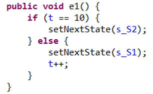
Figure 5: Integer incrementor.
An additional remedial action that can be used to avoid ending up in the situation of Figure 5 is the usage of assertions to detect potentially unbound variables.
The initial attempt at architecting the Fault Protection model did not consider the limitations of the tool chain. The initial model used complex elements and diagrams such as sequence diagrams, nested logic (hidden If statements), complex state machine model elements (e.g. decision nodes), and global variables. Simulation artifacts began overtaking the model because of the complex elements and nested logic. Additionally, the current version of the SysML to Java code transformation tool is limited to interpreting composite Statecharts, transition guards, signals, and opaque behaviors. Thus, the model architecture was refactored to use explicit logic and simple Statechart elements, leading to a much cleaner and clearer architecture that can be simulated and model-checked.
The fundamental drivers of the modeling task are patterns and practices that lead to efficient model checking (keeping the state space as small as possible). Model checking should allow an exhaustive search to be performed in reasonable time and with acceptable memory consumption. The goals are to make checking of large system models a standard practice that is accessible to a wider audience of engineers and to make using the tool easy by automating the process without requiring highly specialized skills to produce and optimal representation of the system and properties to be checked..
Currently, jpf-statechart (in scriptless mode) does not distinguish between external and internal (created by entry/do/exit behaviors and transition effects) events but checks all combinations of events so no cases of the modeled behavior are missed. However, many paths irrelevant for the specification of the system behavior are explored.
With this distinction, the model checker would have, for every state configuration, only a limited number of internal events (which are possible in a particular state) available when generating events during transition exploration. For example in Figure 6, assuming that e1, e2, e4, e5 are external events and e3, e6 are sent by the behavior of state S1, while e7 is sent by the behavior of state S2, then the model checker could ignore e6 when the state configuration is {S2, S4}.
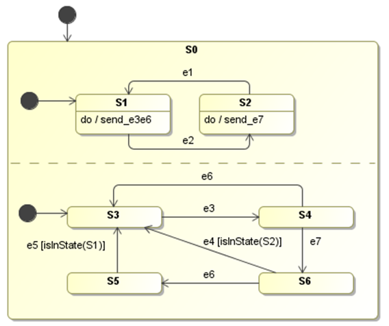
Figure 6: Multiple Paths to reach a state.
Guards are critical in keeping the state space limited. A goal to reduce the state space even more is to further develop jpf-statechart to take into account the internal signals that are sent in behaviors. One possible solution is to annotate trigger methods with states in which they are enabled.
This demonstrates good modeling for model-checking practice: Use guards to encode the knowledge of the model about internal events. Without guards, the model checker would exhaustively explore the complete state space, whereas in the final run-time system the entire state space would never be checked since only a limited number of events will occur at any given moment in time. Adding guards that limit the number of possible transitions results in a two-fold advantage. First, the state space that is explored is drastically reduced, decreasing the time and memory used for model checking. Second, including the guards in the final implementation ensures the system will never end up in an “unexpected” state if an out of order event occurs. In both cases the complexity of the system is reduced, allowing the amount of involved testing to be reduced and off-nominal behavior to be limited (it is worthwhile to investigate how the introduction of model checking affects traditional test strategies). It is important to note that guards also help when doing an initial validation and verification of the model using simulation. For example, in multiple circumstances, the model could not be simulated after adding a guard, which pointed out a model error or bug. The guards also validate the modeler’s assumption on the behavior of the model.
Multiple versions of the fault protection system’s response queue were modeled in order to find a pattern that could be executed and model checked. The response queue was initially modeled using opaque behaviors with ‘if inState’ code inside of states – this actually represents implicit Statechart states that cannot be considered by jpf-statecharts but only by JPF-Core, therefore increasing the state space. Now the response queue is modeled explicitly with multiple nested states and ‘inState’ guarded transitions. It was found that both methods work for simulation and JPF (because JPF can interpret the code inside of opaque behaviors); however because the latter method is explicit (it does not have hidden guards in the code) and limits the state space with guarded transitions, it was chosen for the queue pattern.
This is the first part of the article originally published at http://dl.acm.org/citation.cfm?id=2560583
Image source http://www.jpl.nasa.gov/missions/soil-moisture-active-passive-smap/


 Why do MBSE? What is Model Based Systems Engineering? How to define and implement effective process? What are fundamental concepts and enablers of MBSE? INCOSE made brochure, explaining why MBSE should be used instead of paper-based approach. Models are created to deal with complexity. In doing so they allow us to understand an area of interest or concern and provide unambiguous communication amongst interested parties.