This document proposes structuring and styling rules that help writing requirements using the SysML language as well as specific MagicDraw capabilities that support this process.
Prerequisites: basic MagicDraw knowledge; basic knowledge of the SysML language requirements part.
The biggest issue users have when they start writing requirements using the SysML language is that there is little information on how to properly layout the requirement diagrams, how to relate them to other UML or SysML diagrams, how to structure the requirements project into layers, what the granularity of the requirements should be, how evolution of the requirements should be handled, etc. In other words, there is quite a lot of information describing language concepts themselves, not so many practical experiences describing how to use that language in the real-world.
In this guide, we share No Magic, Inc. experience using the SysML language for developing MagicDraw product itself. We hope that this document can lead to a two-way sharing of experience and ideas – if you as a reader have suggestions or questions, you are very welcome for a discussion.
Requirement Layers
Every product (tool, plugin, or framework) should have a single MagicDraw requirements project which should hold requirements for the current state of the product. The recommended name for the requirements project is ” Requirements”, e.g. “Cameo Infrastructure Requirements” or “MagicDraw Requirements”.
The requirements within a project should be expressed in the “shall” form stating how the system should work instead of specifying what has to be changed from the current state.
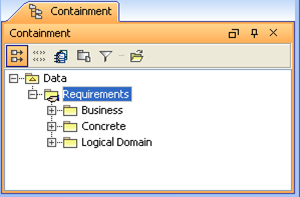
Figure 1 Package structure of a requirements project.
A requirements project should have a single root package called Requirements which should contain all the requirements under it (directly or indirectly). It should be shared so that the development and QA could use the requirements for their needs.
The Requirements package should have three packages under it (see Figure 1):
-
Logical Domain. This package should contain domain models expressed in UML class diagrams. More information on this is provided in the following chapters of this document.
-
Business. This package should contain high-level (business) requirements. Requirements in this package should be independent of the requirements specified elsewhere in this project.
-
Concrete. This package should contain requirements that implement or satisfy the business requirements. Requirements in this package should only depend on the requirements specified in the Business package via the «derive» relationships. For example if the business requirement is ‘The system shall track changes in projects’, then its counterpart in concrete requirements could be ‘The system shall support element-level versioning’.
Figure 2 summarizes what has been described so far. It shows the dependencies between the requirements in top-level requirement packages expressed as «derive» relationships.
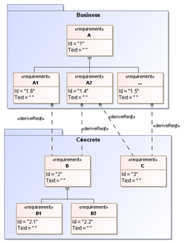
Figure 2 Dependencies between requirements in top-level packages.
Contents of the Business Requirements Layer
The Business requirements package should have a single non-derived requirement root element (we will further refer to this element as to root requirement in this document). There can be other root requirements but they can only be derived directly or indirectly from the root requirement. In order to emphasize that there is only a single true root element, other root elements should be moved into packages which represent logical units of a system. Non-derived and derived root elements should be owned by the packages. Other requirements should be owned by requirements. In other words, the requirement should either be a root requirement, or belong to the root requirement directly or indirectly, or be derived from the requirements that belong to the root requirement directly or indirectly.
The root requirement should be named the same as the framework/tool/plugin is named (without version), e.g. Cameo Infrastructure.
There should be a single diagram directly under the Business package or owned by the root requirement. It should be the starting point for reading framework/tool/plugin requirements (e.g. its name could be High-Level Requirements). This diagram should have a symbol representing the root requirement and (possibly) its directly owned requirements.
The sample structure of the Business package is shown in Figure 3. There is a root requirement under this package and a single diagram graphically representing it. There is also a bunch of packages which contain requirements derived directly or indirectly from the root requirement.
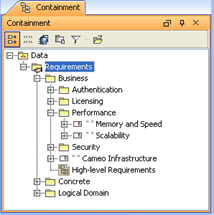
Figure 3 Structure of the Business package.
Contents of the Concrete Requirements Layer
As stated earlier, requirements in the Concrete package should have requirements that “implement” or satisfy requirements in the Business layer. Requirements in this package should be derived from the requirements in the Business package. Generally, the same rules from the Business package apply here except that there is no root requirement. All the requirements here are derived and should be owned by packages which on their own should be owned by other packages or the Concrete package. As for the contents of the packages under the Concrete package, they should contain both functional and GUI requirements.
Sample structure for the Concrete package is shown in Figure 4.
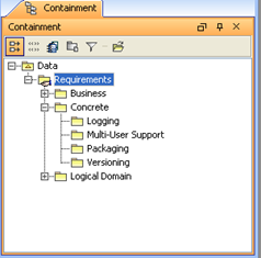
Figure 4 Structure of the Concrete package.
Domain Models
Domain models should be owned by the Logical Domain package (see Figure 5). Each package should be structured on its own. Package structure should be created in accordance to the logical parts of a modeled system.
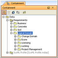
Figure 5 The Logical Domain Package.
Domain models are be modeled using class diagrams. Sometimes state machine, activity or sequence diagrams are also used in addition to class diagrams. Class diagrams should be owned by the packages residing in the Logical Domain package. Sometimes it is needed to describe the overall domain model of a particular feature in several aspects. In such a case each aspect shall be modeled in a separate class diagram. The diagrams describing separate aspects should still be owned by the same package that holds classes describing the feature.
Requirement Diagram Ownership
Requirement diagrams should be owned by the requirements they represent. In some cases requirement diagrams can be placed next to the represented requirements. This approach is less recommended as the diagram in this case is not kept together with the requirement and all refactoring-related actions should be performed twice on both the requirement and the diagram (e.g. moving a requirement to new location will require moving the diagram to another location too). This may lead to situations where diagrams are scattered over the model in different places than the represented requirements. This would make reading the requirements model quite a hard task.
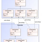
In Figure 6, the root requirement is named Cameo Infrastructure. There is a diagram High-Level Requirements that represents this requirement and is owned by the Business package. There is also a diagram called Scalability Requirements, which is owned by the Scalability requirement and it graphically represents the Scalability, Storage, and Distribution requirements and their subrequirements.
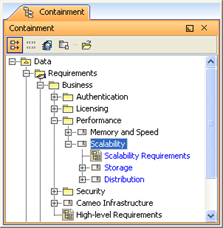
Figure 6 Ownership of Requirement Diagrams.
Element Layout in Requirement Diagrams
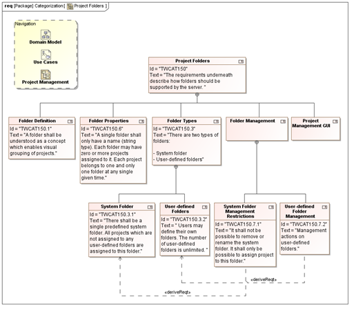
Figure 7 Requirement diagram areas.
There should be mainly two areas in each requirement diagram (see Figure 7 for an example):
-
Navigation area. There should be an area in the diagram for putting links to/from related diagrams (e.g. there is a yellow rectangle shape at the top left corner in the diagram shown in Figure 7 holding hyperlinks to domain models and related requirement diagrams). If the requirement diagram refines a requirement from another requirement diagram, the Navigation area should have a hyperlink to that diagram.
-
Requirements modeling area. There should be a single root node and a certain level of its owned requirements in a single requirement diagram. One nesting level is recommended. However, if the number of requirements in each nesting level is small (e.g. 1-4 requirements), there can be more nesting levels in a single diagrams. Requirements that have more than 5 owned requirements should be refined in separate diagrams. Having more than one root node would possibly mean that the navigation area would contain backlinks to different contexts which could possibly confuse the reader if he/she wanted to navigate to objects from a single context. Requirements from other contexts, e.g. derivation targets, should be of a different color (for example the color could be yellow as shown in Figure 7). This is required to distinguish the requirements in the current context from the requirements in other contexts.
Requirements in the Requirement modeling area can be laid-out in three different ways:
-
Horizontally. In this layout, requirements of the same nesting level are laid-out horizontally. Nested requirements are positioned below the owning requirement by aligning the center of the whole row of requirements to the center of the owning requirement. This layout type is handy when requirement texts are not large (and they should not be large; if they are – they should be decomposed into several requirements). Requirements in this layout are read in the left-to-right, depth first order. Horizontal layout is the
recommended layout. A sample of horizontal requirement layout is depicted in Figure 7.
-
Vertically. In this layout, requirements of the same nesting level are laid-out vertically. Nested requirements are positioned below the owning requirement by shifting the whole column of requirements to the right relatively to the owning requirement. This layout type is handy if there is a list of requirements whose texts take a considerable amount of space. A sample of vertical alignment is depicted in Figure 8.
-
Horizontally and vertically in a single diagram (mixed layout). Sometimes it is useful to mix horizontal and vertical layouts in a single diagram, e.g. for saving diagram space. Figure 9 shows a sample requirement diagram where requirements Reusable Dialogs, General Requirements for a Dialog Window, and Open Dialogs Only When Connected to Server are laid-out horizontally, where others are laid-out vertically to save space (this is much more readable and understandable than organizing the requirements horizontally in this particular case).
Note: This section only describes three layouts that are most common, however depending on the situation you can layout requirements differently, e.g. when you have only derived requirements in a single diagram you may want to use something different.
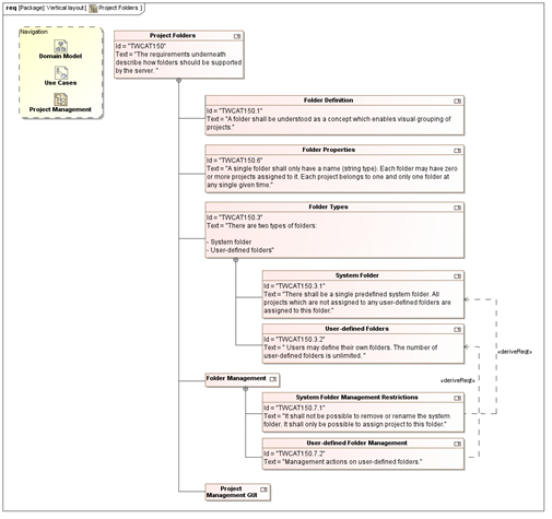
Figure 8 Vertical requirement layout.
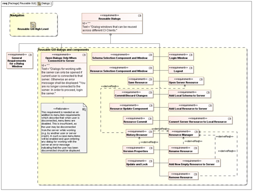
Figure 9 Mixed requirement layout.
Requirement Hyperlinking
Requirements should have hyperlinks to the requirement diagrams in the following cases:
-
If the requirement is refined with another diagram, then it should have a hyperlink to the refining diagram;
-
If the requirement B is derived from the requirement A then both A and B should have hyperlinks to the diagrams in which they are described if these diagrams are different. The diagram where A is described should have a symbol representing B and the derivation path to B. The diagram where B is described should have a symbol representing A and the derivation path to A.
Using SysML Requirements Tables
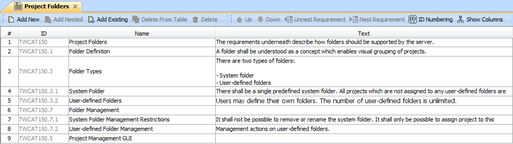
Figure 10 Requirements table.
In some cases, requirements tables (see Figure 10) can be used instead of ordinary requirements diagram. This diagram is mostly useful in situations where there is a single requirement which has one nesting level of requirements under it. It is worth noting that the table is not capable of showing derivations and other relationships, thus the usage of this table is limited currently. In cases where relationships and related elements need to be displayed, the Generic Table can be used. This diagram is not specifically devoted for requirements, but requirements can be managed in it too.
Modeling GUI Requirements
It is recommended to use a single template for modeling all GUI requirements. An example of such a template is described in this subsection.
A diagram representing requirements for a single window should at least satisfy the following requirements:
-
It should have a single root requirement that groups requirements for the whole window;
-
Requirements directly owned by the root requirement should describe:
-
How the window is opened (by clicking on some button, automatically, etc.);
-
Title of the window;
-
Any informational messages or descriptive texts the window has, e.g. texts that describe what the window does;
-
Data management components. Usually requirements for data tables or data input/editing fields are placed under this requirement;
-
Data management buttons. Buttons that perform actions on entered or selected data are placed under this requirement.
-
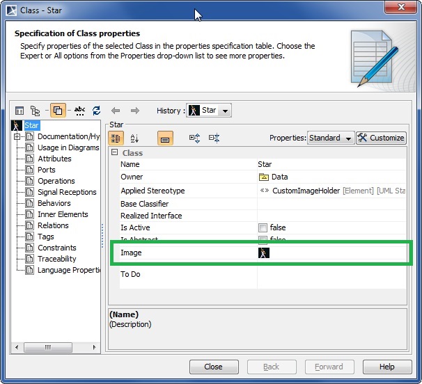
In MagicDraw, it is strongly recommended to use the User Interface Modeling Diagram for sketching the GUI. If this diagram is used, a sketch of the dialog should be created in a separate diagram to which a hyperlink should be created from the root requirement. Alternatively the Diagram Overview shape could be used to display contents of the GUI in the requirements diagram (see Figure 11 for an example). If the User Interface Modeling Diagram cannot be used, there should be a sketch of the dialog placed in the same diagram and it should be attached to the root requirement.
A sample requirements diagram of the Open Server Project window is shown in Figure 11.
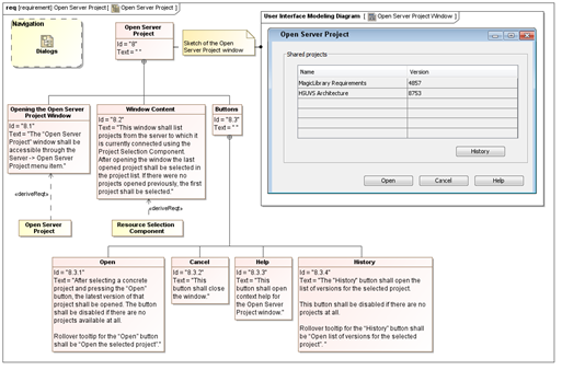
Figure 11 GUI requirements for a single window.
Requirement Decomposition
When writing requirements in SysML a question when to decompose a requirement into other requirements arises quite often. The rules here are as follows:
-
if some part of the requirement is going to be used somewhere else, e.g. some other requirement derives from it, or it is a subject to decomposition itself, then the requirement should be decomposed into smaller requirements
-
if the requirement has information from different (sub)topics, it should also be decomposed into subrequirements
-
if parts of the requirement are not used by any other requirement and the requirement holds information that naturally describes the same topic or thing, but the text of the requirement becomes too big (e.g. 8-10 sentences), it should still be decomposed into several requirements for better readability
«satisfy» relationship
The «satisfy» relationship describes how a design or implementation model satisfies one or more requirements. A system modeler specifies the system design elements that are intended to satisfy the requirement, e.g. architecture classes satisfying the requirements. This relationship should not be used between requirements.