Darius Šilingas

Avatar

http://lt.linkedin.com/in/dariussilingas

Dec 022014
 

We continue our series of presentations on No Magic, Inc. products and the different domains they cover.

This is a one hour long overview of Cameo Business Modeler product that provides BPMN 2.0 modeling capabilities. At No Magic we believe that the Business Analysts should have products dedicated to their needs. Cameo Business Modeler product family is the answer to this. The presentation introduces the product position in the tool-chain, what kind of capabilities are in Cameo Business Modeler with application samples, and the value product provides.

Recording:

Slides:

Download (PDF, 5.7MB)

The presentation was recorded live at the 2014 No Magic World Conference, May 4-7, Allen, Texas, and delivered by the head of the Solutions Department, Darius Šilingas, PhD.

Nov 182014
 

This is a one hour long tutorial on data modeling. It is well balanced between theory and practice and gives the required information to cover this area and one step ahead.

It covers the following sections:

  • Data modeling concepts,
  • Data modeling techniques,
  • Detailed data modeling,
  • Testing data models with data examples,
  • Data model validation: correctness and completeness,
  • Transferring data model to documents,
  • Usage of data models in business processes,
  • Modeling system context with information flows,
  • Designing GUI based on data models, and
  • Tracking the use of data structures.

Video:

Download slides

The presentation was recorded live at the 2014 No Magic World Conference, May 4-7, Allen, Texas, and delivered by the head of the Solutions Department, Darius Šilingas, PhD.

Oct 232014
 

Systems of Systems Engineering (SoSE) is a set of developing processes, tools, and methods for designing and re-designing complex systems. It’s a challenging practice that requires sophisticated tools like MBSE, SysML, and modeling software like Cameo Systems Modeler.

The session demonstrates:

  • System definition vs. system usage
  • Modeling Internal block definition (ibd) diagrams (including tool usability tips & tricks)
  • Using already defined system in the context of another system
  • Modeling SysML 1.4 ports (proxy port, full port) and flows
  • Structural breakdown of a system

The session was hosted by Dr. Darius Silingas, Head of Solutions Department at No Magic, Inc.

Learn more at: http://www.nomagic.com/mbse/

This webinar is part of a series of webinars on Model-based Systems Engineering: from theory to best practices, covering the most important aspects of systems and SoS modeling, analysis, and simulation.

Series consists of four webinars, each focusing on different aspects and delivered by the best experts in the field:

Webinar 1
Model-based Requirements engineering
September 18 14:00 GMT
Webinar 2
Systems of Systems Engineering
October 16 14:00 GMT 
Webinar 3
Engineering analysis on SysML Models
November 6 15:00 GMT
Webinar 4
Defense Systems Engineering with NAF and SysML
December 11 15:00 GMT
May 262014
 

ANTI

In this series of posts we will explore several cases presenting real-life business process examples representing common anti-patterns in business process modeling and demonstrating how to improve the examples by applying best practices.

Anti-Pattern #5: Poor Diagram Layout

Last, but not least, in practice there are many issues with business process diagram layout. You can spot many anti-patterns like different sizes of similar type elements, uneven spaces between elements, long, bended and crossing lines, etc. All of these anti-patterns in layout do not change the content of the business process but they make a diagram very difficult to read and understand. Figure 1. represents a typical layout, which contains many of these anti-patterns.

Figure 1. An example of a poor layout diagram for a business process Organize Seminar containing various layout issues such as slalom, different symbol sizes, uneven spacing and bended lines (see Figure 2. for a refactored version)

Figure 1. An example of a poor layout diagram for a business process Organize Seminar containing various layout issues such as slalom, different symbol sizes, uneven spacing and bended lines (see Figure 2. for a refactored version)

The diagram can be improved to comply with the best practices in layout as presented in Figure 2, which was already used to explain multiple levels of details. One very important issue in Figure 6 is so called “slalom” – a lack of consistent direction of flow, which among other things makes it very difficult to differentiate the main and alternative scenarios.

s1

Figure 2. The diagram improved to comply with the best practices in layout

In Western culture, a typical flow should be oriented either top down or from left to the right. We prefer top down as the first direction because it enables to balance use of space – the activity names’ text naturally flows from left to the right, and the sequence flows then progress in a top down direction. Missing a clear direction of flow also indicates that the modeler probably captured all the details at once, while a best practice is to address the primary ‘happy day’ scenario first and address alternative scenarios only afterwards.

Summary

We have analyzed five practical cases presenting original business process model examples suffering from particular anti-patterns, suggested best practices that help to get rid of these anti-patterns, and improved the original versions into better quality business process models that comply with the best practices. The presented cases deal with inconsistent naming, large process diagrams, inconsistent use of gateways, inconsistent use of events, and poor diagram layout. We think that such example based approach to analysis of typical anti-patterns and resolving them is the most efficient way to teach business process modeling best practices. The presented anti-patterns should not be treated as an extensive list but rather as examples of a starting initiative. We hope that posts will motivate more research and publications on improving BPMN models in both breadth (other cases) and depth (more technical details) directions.

About authors

The case was made by and the examples are taken from extensive authors’ (Darius Šilingas, Ph.D. and Edita Milevičienė) consultancy in financial, telecommunication, government, and information technology domains helping No Magic customers to adopt MagicDraw and Cameo Business Modeler products for efficient business and software modeling.

May 082014
 

ANTI


In this series of posts we will explore several cases presenting real-life business process examples representing common anti-patterns in business process modeling and demonstrating how to improve the examples by applying best practices.

Anti-Pattern #4: Inconsistent Use of Events

Events are fundamental elements in BPMN – each process begins with a start event, finishes with one or more end events, and potentially reacts to a number of intermediate events happening during the process. While events themselves are not very tricky, deciding at which process level to put the event initiating a process or choosing a proper scope of an intermediate event might be done incorrectly. In Table, we list two common anti-patterns with events usage and the best practices for improving them. Figure gives an example of a business process fragment with anti-patterns and after improvements according to the best practices.

Typical Event Usage Anti-Patterns and Best Practices

Anti-Pattern

Best Practice

Event outside and inside process – repetition makes it redundant; a formal interpretation would require the event to happen twice.

Initiating event out of process description – it is easier to read a diagram and understand when/why a sub process needs to be performed.

Repeating events – complicates diagram and its maintenance.

A subprocess with attached event – enables to clearly define the scope of an event.

Inconsistent Use of Events

An example of a business process Administer Bad Loan fragment with anti-patterns in events usages and an improved version complying with best practices

About authors

The case was made by and the examples are taken from extensive authors’ (Darius Šilingas, Ph.D. and Edita Milevičienė) consultancy in financial, telecommunication, government, and information technology domains helping No Magic customers to adopt MagicDraw and Cameo Business Modeler products for efficient business and software modeling.

May 062014
 

ANTI


In this series of posts we will explore several cases presenting real-life business process examples representing common anti-patterns in business process modeling and demonstrating how to improve the examples by applying best practices.

Anti-Pattern #3: Inconsistent Use of Gateways

Gateways are very important as they control the branching of a business process sequence flow based on data or upcoming event(s). They also specify a connection point from the sub process end events to the external process. In practice, we see a lot of issues in using gateways. Often gateways are omitted and multiple sequence flows go in to/out of an activity, which impairs readability and interpretation. In our opinion, a frequent convention of using a question for a name of a gateway and Yes/No on branched sequence flows is wrong because it makes not possible to connect the names to the names of end events of a preceding sub process (Yes and No are not very good names for the end events). Also, we observe a frequent misunderstanding on how to use event based gateway and workflow patterns related to it. In Table 1, three common anti-patterns in using gateways are presented together with corresponding best practices, and Figure 1 show fragments of a business process before and after applying best practices.

Table 1. Typical Gateway Usage Anti-Patterns and Best Practices

Anti-Pattern

Best Practice

Multiple incoming/outgoing sequence flows – makes it difficult to understand how many flows are required to come out/in.

Always use gateways for branching/merging – improves readability of the diagram and explicitly indicates control points.

Event-based gateway with outgoing sequence flow unconnected to event – makes it ambiguous when the alternative sequence flow should be taken.

Apply Deferred Choice pattern – all the sequence flows after event-based gateway should be connected to events. Use timer event to model cases when expected event does not happen.

Gateway unsynchronized with preceding subprocess ends – shows inconsistency between sub process details and its usage in a larger process.

Apply Internal Business Error pattern with synchronized end/branch naming – makes it very straightforward to consistently use gateways and sub processes.

Inconsistent Use of Gatways

Figure 1. A fragment of a business process Sell Licenses with anti-patterns and an improved version complying with best practices

About authors

The case was made by and the examples are taken from extensive authors’ (Darius Šilingas, Ph.D. and Edita Milevičienė) consultancy in financial, telecommunication, government, and information technology domains helping No Magic customers to adopt MagicDraw and Cameo Business Modeler products for efficient business and software modeling.

Mar 112014
 

ANTI

In this series of posts we will explore several cases presenting real-life business process examples representing common anti-patterns in business process modeling and demonstrating how to improve the examples by applying best practices.

Anti-Pattern #2: Large Process Diagrams

The second fundamental thing that needs to be reviewed is the complexity of process diagrams. While BPMN supports modeling processes in multiple levels of detail, many practitioners are used to “everything in one page” style, which impairs overview and makes it difficult to understand and analyze the process. Psychologists have determined that the best number of visual elements to focus on in one diagram is 5±2. In practice this rule is rarely followed. We think that it is quite practical to increase this number to 7±4, but consulting various organizations on business process modeling, we have seen extreme cases of business process diagrams with up to 450 (!) tasks. Such large diagrams make it very difficult to analyze them and spot the issues – the value of visualization is lost. In Figure 3, a presented example of a large diagram contains a number of inconsistency issues such as lack of Confirm Seminar activity that is symmetric to existing Cancel Seminar activity, a non-ending loop for registering participants after Decision Deadline, uneven levels of detail for announcing seminar (the first four tasks) and canceling it (one compressed subprocess), no clear distinction of early and late registration and others. However, it is rather difficult to spot such issues if you are analyzing a large complex business process diagram – you are happy that you have managed to read and understand it and do not question its quality.

large  Figure 1. A large business process diagram Organize Seminar with 16 activities

A key best practice, which enables getting rid of complex diagrams keeping all the important information about business process tasks, is using several layers of detail. Figure 2 demonstrates an improved version of the example given in Figure 1, which uses subprocesses with additional diagrams assigned for each of them. In such an approach, you can decompose a very large (and typically inconsistent!) business process into a simple and consistent process structured in several levels of detail. For example, a business process with three levels of detail following the rule of up to 10 activities in one level may contain 103 = 1000 tasks.

s1 s2

Figure 2. A improved business process diagram Organize Seminar with 7 sub processes and sub process Announce Seminar specified in a separate diagram

About authors

The case was made by and the examples are taken from extensive authors’ (Darius Šilingas, Ph.D. and Edita Milevičienė) consultancy in financial, telecommunication, government, and information technology domains helping No Magic customers to adopt MagicDraw and Cameo Business Modeler products for efficient business and software modeling.

Mar 042014
 

ANTIBusiness Process Model and Notation (BPMN) is already acknowledged as a de facto standard for business process modeling. However, it still takes a long journey to increase the maturity of business process modeling practice. In practice most business analysts do a lot of mistakes that make their BPMN models over complex, difficult to understand and maintain. Therefore, it is important to understand the common mistakes, which we refer to as anti-patterns, and how to get rid of them applying best practices. Practitioners learn best in an example-driven approach.

In this series of posts we will explore several cases presenting real-life business process examples representing common anti-patterns in business process modeling and demonstrating how to improve the examples by applying best practices.

Anti-Pattern #1: Inconsistent Naming

The first fundamental thing that needs to be reviewed is BPMN element names. It is quite typical that modelers use nouns for naming activities or use different naming style for the elements of the same type in different places. As several philosophers stated, “the language we speak shapes our thinking”. This applies well to business process modeling context – it is very often that modelers misuse BPMN elements, which is reflected in inconsistent naming. Table examines some typical anti-pattern in naming and corresponding best practices/patterns.

Some Naming Anti-Patterns and Best Practices

Anti-Pattern Best Practice
Noun based activity name – indicates that element is an event, data object, or process area as opposed to activity. Strong verb + domain specific noun – emphasizes achieving a discrete goal after performing work.
Gateway named as activity – indicates that a gateway represents a task, which determines the choice. Unnamed gateway – it is merely a branching element that does not perform any work, so it should not be named (except for referencing).
Words and/or in activity name – indicates multiple activities captured in one activity. No conjunctions in names – raise name abstraction level or split into two subsequent/alternative activities.
Long activity name – indicates that details of activity are emphasized instead of the goal; orients diagram towards textual document.  Short name + documentation – the name should emphasize the goal, and details of activity can be captured in comments or documentation.

For an experienced business process modeler, solving naming conventions may seem to be easy. However, in practice we face inconsistent naming issues in almost every organization that adopts BPMN as a standard for specifying business processes. A typical case of business process model with anti-patterns presented in Table and refactoring it is presented in Figure.

Business process Make Loan Proposal with inconsistent naming and an improved version complying with naming best practices

Business process Make Loan Proposal with inconsistent naming and an improved version complying with naming best practices

We analyzed only a few most common naming issues – in practice, you will also face problems with inconsistent naming of events, data objects, participants, messages, etc. For organizations that are adopting BPMN as a standard, it is highly recommended to establish naming guidelines and perform regular review of BPMN models to ensure that these guidelines are followed.

It is important to note that MagicDraw and Cameo Business Modeler enables modelers to specify model validation rules that enable automated detection of some anti-patterns.

About authors

The case was made by and the examples are taken from extensive authors’ (Darius Šilingas, Ph.D. and Edita Milevičienė) consultancy in financial, telecommunication, government, and information technology domains helping No Magic customers to adopt MagicDraw and Cameo Business Modeler products for efficient business and software modeling.

Dec 182013
 

This is the second part from two part article. For the first part click here.

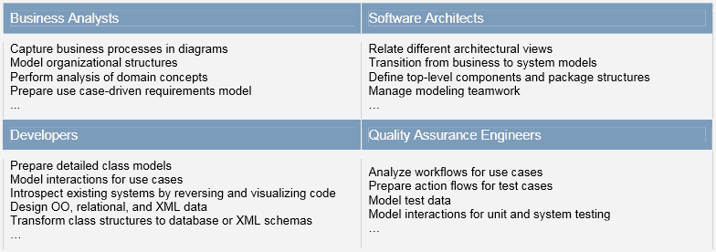
Best Practice #2: Focus on the Most Valuable Modeling Artifacts

The cynic knows the price of everything and the value of nothing. [Oscar Wilde]

The second best practice supplements the first one. Knowing what gives value to your role, you also need to know what modeling artifacts have long-term value and need to be maintained. The others might be used for instant needs and thrown away later. Understanding this is really important, since trying to keep too many irrelevant modeling artifacts synchronized with actual source code quickly becomes a pain in the … archive. We believe this synchronization headache makes many people think they don’t need modeling tools and are fine with whiteboards. But they soon get lost in whiteboard discontinuities.

However, analysis model artifacts are of high value and should be consistently modeled and maintained, including analysis artifacts such as:

  • Domain entity relationship (ER) class diagrams;
  • Use case models;
  • Activity diagrams for use case scenarios.

Business analysts perform domain analysis by modeling domain entities and their relationships using simplified class diagrams. These diagrams serve as a visual vocabulary of concepts. They are also a starting point for the design level data model.

MagicDraw tips

MagicDraw UML tool can even generate a dictionary from class descriptions in HTML format if you provide concise descriptions for modeled concepts.

121813_1129_BestPractic2.png

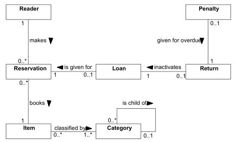
Figure 2 – Domain ER diagram for library management system

The most popular way to analyze functional requirements is the use case method. It starts by identifying user roles – actors – and associating them to their interactions with system – use cases. Many business analysts even start with Use Cases as the best way to capture and document user requirements.

MagicDraw tips

With tools such as MagicDraw, you can even document use case properties like pre- and post-conditions, assumptions, interaction scenarios, and generate a formal, presentable use case document from your model, that can be reviewed by and shared with the business stakeholders.

Abstract use case implementation logic is either defined in text or, for more complex cases, by creating activity diagrams visualizing activity flows for primary and secondary use case scenarios.

MagicDraw tips

As an example, with MagicDraw you can hyperlink use cases to the activity diagrams modeling their scenarios and assign activity diagrams as use case primary and secondary scenarios, which enables including them in generated use case documents. You can decompose activity diagram elements using hyperlinks to detailed diagrams.

 121813_1158_BestPractic3.png

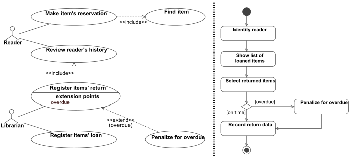
 Figure 3 – Use case model artifacts: use case diagram and activity diagram presenting scenarios for a particular use case Register items return

Technical design model artifacts may be roughly divided into three value-based groups:

  • High value ($$$) – should be modeled and maintained using UML tools;
  • Medium value ($$) – may be maintained or not;
  • Low value ($) – should be used for communication and thrown away.

$$$ – High value design models:

  • Top level structural decomposition of software and hardware environments
    • UML package, component, robustness and deployment diagrams
  • Top level package dependency diagrams
    • UML package diagram
  • Data model
    • UML class diagrams in multiple level of abstraction and details
  • Interfaces for system layers / components / subsystems
    • UML class and component diagrams
  • Dynamic models for interactions implementing main usage scenarios
    • UML activity and sequence diagrams (details, e.g. parameter values, are often left out)

System architects need to bridge the gap between analysis and design. If they are designing layered systems, they may apply robustness analysis, which is based on a simple extension of the class diagram. It makes use of only four elements – actors, boundaries (user or system interfaces), controls (business logic), and entities (data). While entities are more or less identified by the domain ER analysis, the challenge is to analyze actors and use cases, find the system boundaries, and connect them to data entities through controls.

Seeing the forest before going inside it.

121813_1158_BestPractic4.png

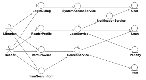
Figure 4 – Robustness analysis for identifying major components in a layered architecture

Architects need to provide the top-level decomposition of software system packages. Modeling dependencies are very important in this case since they set the rules for class responsibilities and interactions and help avoid evil effects like inappropriate coupling and cyclic dependencies. The tools for showing decomposition including dependencies are the package diagram and the component diagram.

Divide and rule! – a strategy used by ancient Roman empire.

121813_1158_BestPractic5.png

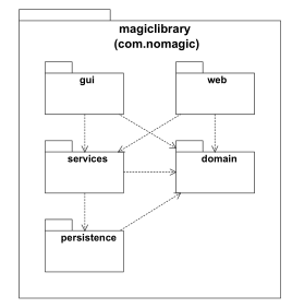
Figure 5 – Package dependency diagram

While the package diagram allows a logical grouping of implementation classes, the component diagram shows system level functional elements. Usually, package and component diagrams leave out utility or library packages. Although packages should be component driven, one package may include multiple components and vice versa. For example, a component might span several packages depending on its size. Component diagrams may also focus on the provided and required components, and on connecting the components together.

It is also important to show how implemented software will be deployed in the hardware and software environment. For this purpose, architects apply deployment diagrams. In UML 1.x, deployment diagrams allowed nesting components on deployment nodes. In UML 2.0, this has been changed, and instead of components, you need to use artifacts that are a physical manifestation of software components. It is a rather common practice to create technology specific UML extension profiles. Profiles enable one to indicate a ‘type’ of an artifact, e.g. <<EJB-JAR>>, and preferably to assign an intuitive icon, which can replace the standard rectangle shape, e.g. a <<database>> icon.

  121813_1129_BestPractic8.png

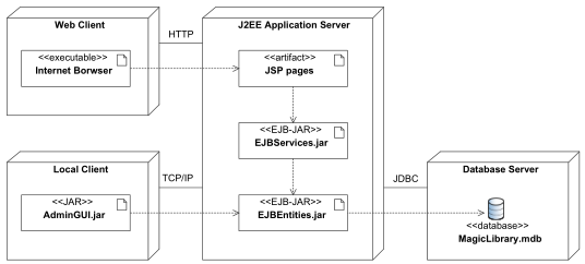
Figure 6 – Top level deployment diagram

Once architects have decomposed the system into packages, components, and deployment artifacts following the layered architecture principle, the next important thing is to specify the contracts between layers. The most important piece here is the method specifications for business logic services, and also for data persistence services if they are not reused. The first step can be done using class diagrams.

121813_1158_BestPractic7.png

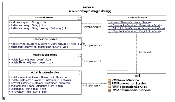
Figure 7 – Interface specifications for business logic layer components

However, using only static class diagrams is not sufficient – you may miss some responsibilities or decompose them inappropriately. Therefore you need to model the dynamic behavior for use case scenarios in order to validate and justify class structures. Applying interaction diagrams – sequence or communication – help in find new methods in existing classes, and in finding new classes for specific responsibilities. Interaction driven modeling is actually a very efficient method, and is the modeling counterpart for test driven programming.

MagicDraw Tips

MagicDraw allows creating new classifiers and adding new methods to existing ones when modeling interactions. You can also easily drag and drop classes to create typed lifelines.

121813_1129_BestPractic11.png

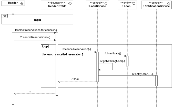
Figure 8 – Interaction diagram for implementing specific use case scenario

$$ – Medium value design models:

  • Structure of UI classes
    • UML class diagram, might be extended for specific technology
  • UI screen transition schema
    • UML state or class diagram
  • Reusable implementation solutions
    • UML class, object, sequence diagrams
  • Logic of important algorithms
    • UML activity or sequence diagrams

During technical design activities, if you go up the layers of the software system, the stability decreases. Detailed models for user interface layers are volatile during design phase – they change a lot, and throwaway prototyping is an approach used. Whether this method is used or not, is it still valuable to model high-level structures of user interface elements without going into details.

121813_1158_BestPractic9.png

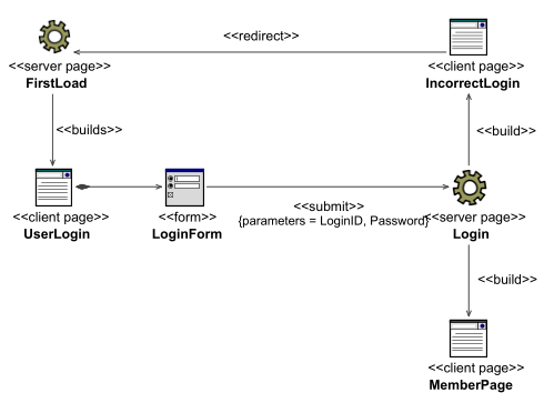
Figure 9 – Structure of Web UI Classes

It is rather difficult to get precise requirements for the system without prototyping its user interface and sketching its navigation schemas. Thus, drawing and maintaining a navigation schema for a system is also a highly useful part of your modeling toolkit. You should apply state diagrams for this task.

121813_1158_BestPractic10.png

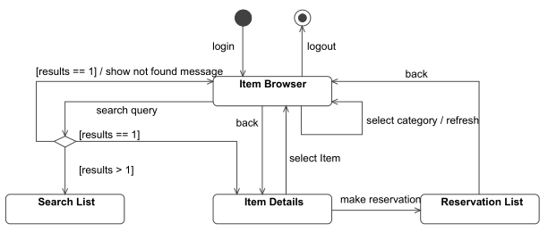
Figure 10 – User Interface Dialog Map

If you go deeper into implementation, modeling is also essential, and it can also be accomplished using UML tools. For example, finding the methods for implementation classes can be accomplished using test-driven programming, which forces you to write unit tests and only then implement the class. Having a model of the tests and test cases helps navigate

through the test process. The testing functionality has excellent support in modern IDE tools. However, UML models illustrating the logic of important algorithms or reusable implementation solutions may also be very helpful for various purposes – analysis, learning, and documentation.

$ – Low value design models

  • Detailed implementation level class modelsq
  • Dependency diagrams for “deep” inner packages and classes
  • Detailed user interface models
  • Interaction diagrams that model all details of implementation
  • Trivial activity or state diagrams

During technical design phase, detailed models change frequently, thus it is better to model, implement, and analyze them in conjunction with programming IDE tools. Most of the technical models can be reversed and visualized automatically from source code using code reverse engineering tools.

MagicDraw Tips

MagicDraw UML supports forward and reverse engineering of various types of code: Java, C++, C#, relational databases, XML schemas. It also provides multiple model visualization tools that in an automated way create multiple diagram types such as package dependency, class hierarchy, and Java sequence diagrams.

The lesson learned: Model artifacts may be difficult to maintain, thus you need to focus on the most valuable ones. Draw and maintain the $$$ value artifacts using UML tools, make your selection of $$ value artifacts that you find useful in your projects, and don’t use for sketching but don’t worry about maintaining $ value artifacts. Maximize your time and your efforts in this way.

Best Practice #3: Model in Multiple Abstraction Levels

Abstraction is the process of reducing the information content of a concept, typically in order to retain only information that is relevant for a particular purpose.

Abstraction is the thought process wherein ideas are distanced from objects.

We model to furnish abstractions in order to manage complexities. Usually there are several levels of abstractions that need to be modeled. The following abstraction levels are usually defined:

  • Analysis Model aka Computation Independent Model (CIM);
  • Design Model aka Platform Independent Model (PIM);
  • Implementation Model aka Platform Specific Model (PSM).

In your UML modeling tool, you should structure your model so that these abstraction levels were clearly separated, easily maintained, and backtracked. Let us show an example of traveling through these three abstraction levels.

The conceptual library management system ER diagram is an example of the Analysis Model (CIM). It shows the concepts that exist in the library system independently of whether it is managed manually of with software system. The links show logical relationships, and we do not model attributes. Even if attributes were modeled, their data types would not be assigned.

121813_1158_BestPractic2.png

Figure 11 – Analysis model of library concepts (CIM)

When designing the software system, we need to derive a detailed data model. It has to be conformant with the analysis model, but some restructuring may be applied based on design decisions. For example, the diagram below illustrates a design model derived from the previous analysis model by making the following changes:

  • Attributes with UML data types were specified for each class;
  • Concepts of Reservation, Loan, and Return were merged into one class Loan;
  • Two specific subclasses of Item – Book and AudioRecord – were added.

This model already defines the complete data structure, but is not technology specific – it’s pure object oriented structure with UML data types, thus not specific to any particular programming language like Java or data storage technology, relational database, or XML.

 121813_1158_BestPractic12.png

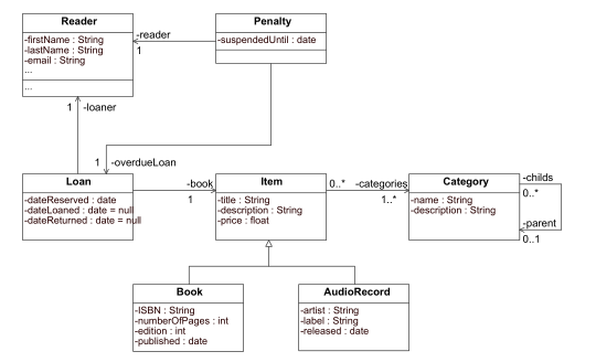
Figure 12 – Design model of a library data structure (PIM)

The next step is to derive the platform specific model, which contains technology specific details and has enough precision for generating executable code. For this kind of modeling, you need profiles with extensions to the UML language, which are technology independent. The example below shows a relational database structure, which corresponds to the design model, with the following changes:

  • Classes were assigned stereotypes <<table>>;
  • UML data types were changed to SQL data types and multiplicities were identified;
  • Primary and foreign key fields were added to classes;
  • The associations were assigned stereotype <<FK>> with properties indicated field mapping;
  • The many-to-many association was changed into intermediate table;
  • The generalization relationships were turned into foreign keys.

121813_1129_BestPractic17.png

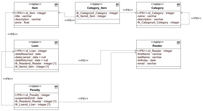
Figure 13 – Implementation model of library relational database schema (PSM)

Although it is possible to model the PSM manually, it is advised to use automated transformations. However, using transformations is a topic of another best practice in the upcoming whitepaper.

The lesson learned:You can model at different abstraction levels. However, it is crucial to decide how many abstraction levels you need for you project – some will be fine with one, but the most will at least require two if not three. Clearly separating abstraction levels in your model projects facilitate maintaining and backtracking related elements.

Best Practice #4: Choose Appropriate Level of Detail

Sometimes less is more.

Figure 14 – Diagrams overloaded with details are difficult to read and understand

Level of abstraction dictates the level of detail. However, with UML modeling tools even within one abstraction level you may choose to show different levels of details. The purpose of what you want to show should drive the choice. Irrelevant elements that can be guessed implicitly should be left out. A common technique is to show a diagram without details of elements but showing the most important relationships between them. Then you can have additional diagrams that focus on the details of specific element.

Let’s go through an example of multiple levels of details so that you can decide, which level is the most appropriate for you.

Step 1

121813_1158_BestPractic15.png

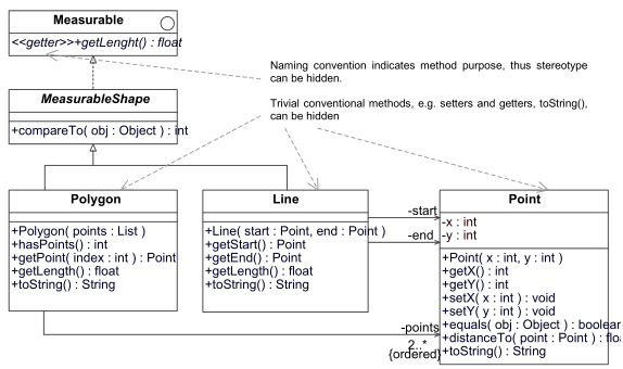
 Figure 15 – Level of Details, Step 1: all implementation details are show

Step 2

121813_1129_BestPractic20.png

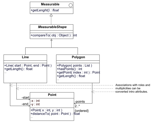
Figure 16 – Level of detail, step 2: irrelevant elements are removed

Step 3

121813_1158_BestPractic17.png

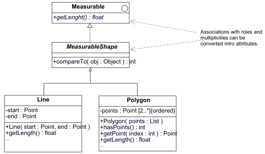
Figure 17 – Level of detail, step 3: unimportant associations are turned into attributes

Step 4

121813_1129_BestPractic22.png

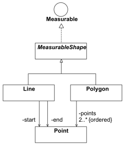
Figure 18 – Level of details, step 4: only class and interface symbols and relationships between them are shown

As you probably agree, removing irrelevant details allows focusing on the essential design elements, which makes diagram easier to read and understand.

It is very important to choose appropriate level of details. We can give the following pieces of advise for controlling level of details in your diagrams:

  • Do not model irrelevant details, such as:
    • Implementation-specific properties;
    • Private class methods and attributes;
    • Conventional methods, e.g. toString() in Java;
    • Utility classes;
    • Elements that can be generated automatically;
    • Getter and Setter methods;
  • Show only the most important associations.

Too detailed models are difficult to understand and keep in sync. Therefore they are rarely used. As a result, it is common to give up their maintenance, thus they become worthless since they do not correspond to the actual design or code.

The lesson learned: Show only important properties of the model elements in your diagrams. Getting rid of irrelevant details improves communication and makes maintenance easier.

Best Practice #5: Model with Style

Style is the way you put together things, not the things themselves.

Software developers follow defined styles for programming, requirements specification, technical documentation, and user manuals. We also need modeling style as well. Adhering to common modeling style makes diagrams easier to read and understand and facilitates teamwork in modeling. Modeling styles includes:

  • Naming conventions;
  • Layout conventions;
  • Choosing appropriate diagrams;
  • Modeling & design principles.

A seminal book published on this topic is “The Elements of UML Modeling Style” by Scott W. Ambler. It gives a bunch of rules that need to be followed when modeling UML diagrams. We will present only an example of improving modeling style and identify the functionality of UML modeling tools that facilitate layout of diagrams.

121813_1158_BestPractic19.png

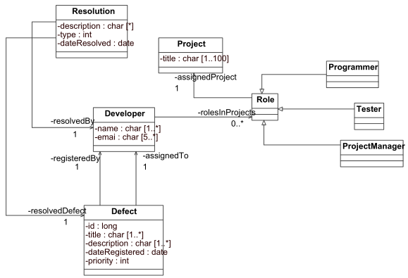
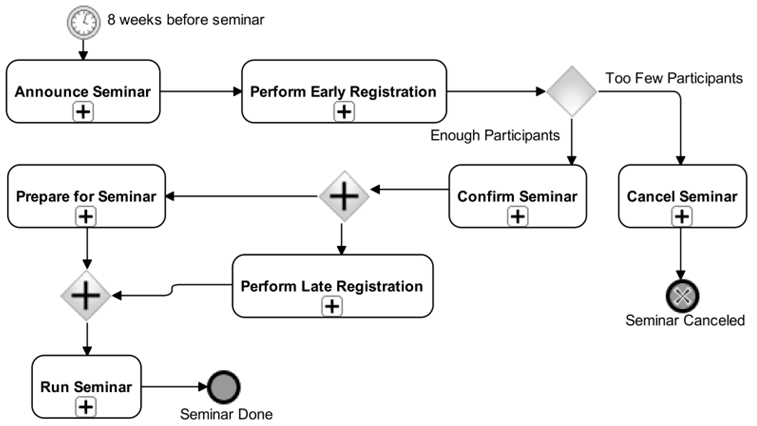
Figure 19 – A diagram which DOES NOT follow modeling style rules

The following problems are apparent in this diagram:

  • Different element sizes are used;
  • Diagram is not symmetric;
  • Long, bent, and crossing lines;
  • Horizontal ungrouped generalization links;
  • Unevenly distributed space.

121813_1158_BestPractic20.png

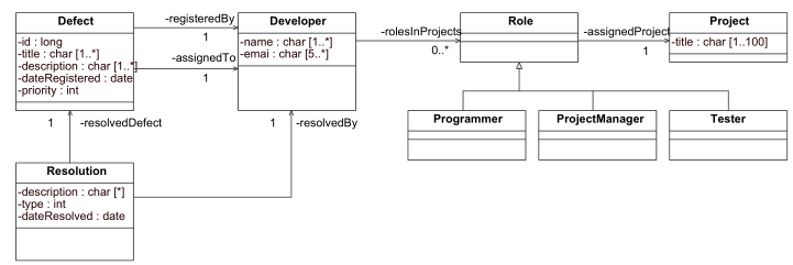
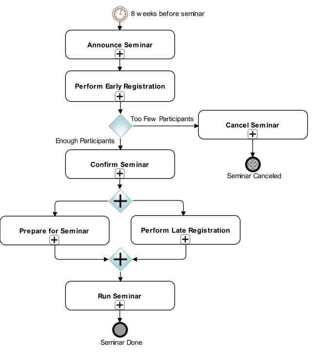
Figure 20 – A diagram, which follows modeling style rules

Some sample modeling style rules:

  • Do not overload diagrams with irrelevant details
  • Split large diagrams into multiple smaller diagrams
    • Diagram should contain 7±2 elements
  • Use colors to identify elements of different type
    • Color may indicate, which development group is responsible for implementation
  • Try to maintain symmetry
  • Model generalizations and realizations vertically
    • Child / implementing class should be below parent / interface
  • Model associations and dependencies horizontally
    • Recommended direction – left to right

There are a lot more rules of thumb on modeling class and other diagrams – check Ambler’s book or his website at http://www.agilemodeling.com/style/

For improving diagram layout, you may apply automated layout tools. However, relative positions of elements in most cases are very important, and most fully automated layout tools do not retain them. We have found out that simple layout functions applied to a selected area or selected elements in a diagram are most helpful:

  • Make sub trees of generalizations, realizations, association;
  • Make elements the same width, height;
  • Distribute space evenly;
  • Align elements to the top, bottom, left, and right;
  • Route paths orthogonally;

Sure, the content is more important than the form. However, sticking to one consistent modeling style makes the content of your diagrams more readable and understandable. Since modeling is both an interactive and iterative activity, diagram readability is essential for improving the content!

The lesson learned: Modeling with style improves the value of diagrams by increasing their readability. There is a lot of modeling style rules that you should apply when modeling different UML diagrams.

In Closing

We have discussed five best practices for applying UML in software modeling. That should be enough information to digest for this time. Please share your feedback regarding presented best practices and the ones from your experience.

Dec 172013
 

Though UML notation is widely recognized as lingua franca for software development, many developers still lack skills for applying it efficiently. Methodologists, practitioners and tool vendors need to share their experience in order to find out ways how to get the most use from modeling and avoid abusing it. With this whitepaper, we start a series of best practices in applying UML that are driven from No Magic expertise in multiple software development projects and buildingMagicDraw tool. We hope that they will help you to change the way you model and make it more efficient!

Software Development and Modeling with UML

Modeling is the core of modern software development. Like every larger engineering task, software development needs a plan. Models serve us as a plan and allow achieving multiple goals:

  • Provide structure for problem solving;
  • Experiment to explore multiple solutions;
  • Furnish abstractions to manage complexity;
  • Reduce time-to-market for business problem solutions;
  • Decrease development costs;
  • Manage the risk of mistakes.

Only when developing very small systems, we may start from scratch and bypass modeling.

You DON’T need modeling: Small one-person projects that do not need to be maintained and will not be transferred to somebody else might not require modeling.

You DO need modeling: Large projects that involve large teams, are developed iteratively, and need to be maintained cannot be successful with out models.

In large projects modeling speeds up implementation while elevating quality and user satisfaction. We model in all software development activities starting from business analysis and requirements definition to testing of the constructed software system.

1a
Table 1– Applicability of UML Modeling Skills

Software systems are constantly growing in size and complexity, and without efficient modeling skills you cannot be successful. A Software Development Magazine Salary Survey in 2005 has revealed that the most important skills needed to produce quality projects and products are architecture modeling and design, which ranked higher than programming, QA, testing, and requirements management.

Recently, we witness intense battles in the field of the software development process. While almost all approaches have gone from the old waterfall approach to iterative development, they argue a lot about formality, roles, activities and artifacts, tools, and which workflows should be emphasized.

1b
Figure 1 – Emphasis on Workflows by Different Softwate Development Processes

Since modeling is the core of development and UML is the de facto standard as the modeling notation, all of those

processes make use of UML. However, the way they use it differs quite a lot. RUP advocates a UML centric approach to software design, which requires UML modeling tools. Agile methods – XP, Scrum, Lean – advocate informal modeling and using whiteboards, paper, and simple text or drawing editors as a compliment to UML tools. While we are in none of these camps, we strongly believe that using modeling tool can help you a lot.

Here is just a short list of helpful UML tool features:

  • Create and maintain a repository of model data;
  • Reuse model elements in multiple diagrams;
  • Create nice diagrams using automated layout functions;
  • Apply built in design patterns;
  • Use automated model transformations;
  • Generate documentation from your model;
  • Analyze your model using automated tools;
  • Enable teamwork within one modeling project.
We believe these features are truly beneficial in all software development processes if you take a proactive approach to modeling. In the next section, we present 5 best practices for modeling with UML.

Best Practices

Experience is the worst teacher – it always gives the test first and the instructions afterward.

Let’s get some instructions before you apply UML in your projects – you can count on our experience, which resulted in the best practices presented below.

Best Practice #1: Apply a subset of UML relevant to your role

80%–20% rule: 80% of the users apply only 20% of the features.

UML 2.0 defines 13 diagram types and each of them uses a bunch of UML elements. You can find many people arguing that UML has grown too large and too complex. Well, it definitely evolved and contains more modeling elements if compared to its original version. However, it is important to recognize that you don’t in most cases need the full capabilities of UML. The famous 80%–20% rule holds here as well – 80% of modelers will be fine with 20% of UML. Which 20% is yours is dictated by your role and that role’s need for specific UML modeling skills.

Table 2 – Applicability of UML Modeling Skills

1u

Business analysts will mostly apply use case and activity diagrams for capturing processes and requirements, also very simple class diagrams for domain analysis and state diagrams for defining lifecycle of important business objects. They will need extensions of UML for modeling enterprise architecture concepts like organizational structure or business goals.

Software architects will apply all UML diagrams, but they would not go into implementation details. Architects need to capture overall system structure in high level concepts. In most cases, they will be fine with package, component, and deployment diagrams; and will model only the most important classes and interactions. When building classical layered systems, they might use the robustness diagram – a simple extension of the UML class diagram – for identifying major components in interfaces, business logic, and data layers.

Developers will not model all parts of the system, but they would go into low level implementation details on the most important system parts, e.g. data structures. They use detailed class and interaction diagrams. Most probably, they will also need UML extensions for capturing technology specific details like relational database structures or XML schema elements.

Quality assurance engineers need to analyze UML diagrams prepared by business and system analysts, and base their test cases on use case workflows. They will need object diagrams for modeling test data and activity diagrams for modeling test action flows and rules. For those who do more technical testing like unit testing (though in the most of recent approaches it is done by programmers), stress or load testing might need to model interactions using either sequence or activity diagrams.

The lesson learned: You don’t need to know and use the complete UML specification. Learn and apply only the subset that is relevant to your role!

This is the first part of the Best Practices for Applying UML article. Follow this link for the second part.

Nov 132013
 

The large drawback in adopting of any method is lack of good practical feedback. This presentation provides practical information, which is result of long years of experience in: consultations, training, and product management.

This set of slides was used at BPM Europe 2013 for a half day workshop on this topic. Please note that an essential part of the workshop was a practical assignment on mapping textual description of a business process Recruit New Employee to BPMN business process in two levels of detail. The practical assignment is not a part of this presentation.