Osvaldas Jankauskas

Avatar

https://www.linkedin.com/in/osvaldas-jankauskas-6b150bb6

Mar 032017
 

When you need to visually identify the particular information of the element, you should go to the specification of that element or display this value in the compartment of that element symbol. Starting with 18.5 version of MagicDraw, this can be achieved in more simple and compact way – by changing the element’s symbol appearance on a diagram using legends.

Legends provide a quick way to visually distinguish elements. Symbol colors and icons defined in a legend allow you to instantly indicate and recognize information about elements, such as property values. Legends have been significantly improved with MagicDraw 18.5. You can now change symbol appearance according to the specified condition. See Figure 1.

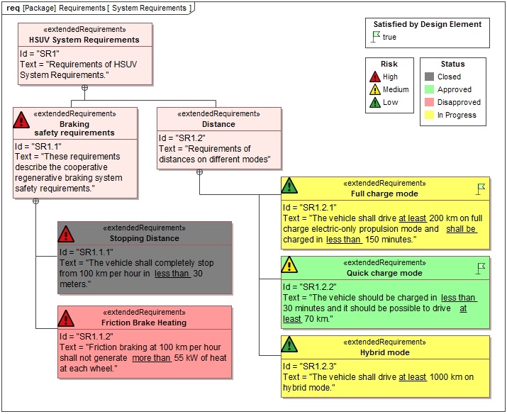
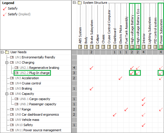
Figure 1. The multiple aspects of the requirement in one view.

As you can see in Figure 1, the diagram represents multiple aspects of requirements. The properties of each requirement are represented through symbol colors and icons. For example, the “Quick Charge Mode” requirement is of medium risk (yellow warning icon), has the approved status (green fill color) and is satisfied by design element (green flag icon). All of this information can be seen in one diagram, at a glance. Therefore you don’t need to check it in the Specification windows of individual elements.

Legends creation.

You can create legends by using the button located in the “Common” group of the diagram pallet. Legends serve as grouping elements for a set of visualization elements called legend items. Legend items can be created directly from a legend symbol, as illustrated in Figure 2.

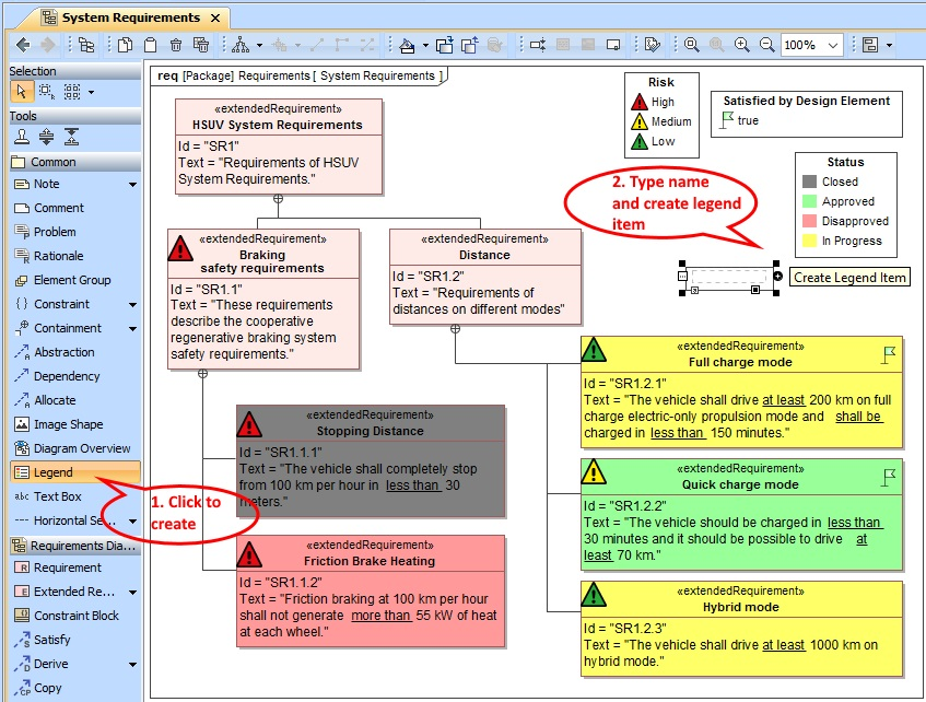
Figure 2. Creating legend and legend items.

A legend item defines the representation of an element symbol. In order to change symbol appearance, you can specify symbol fill, line, background colors and icons. Legend items can be applied to elements in two different ways:

  • By selecting particular elements from the model
  • By specifying a condition to evaluate model elements

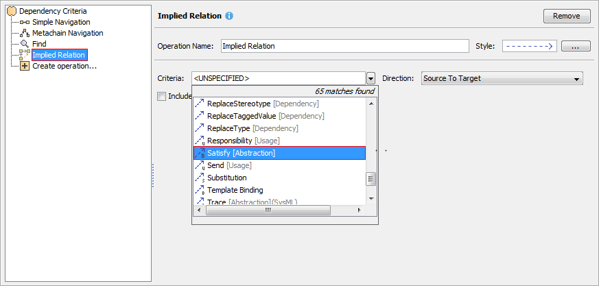
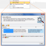
The second method utilizes a new Property Test operation which simplifies the specification of the condition that checks the value of an element property. All you need to do is select an element type, choose the desired property and specify its value. See Figure 3.

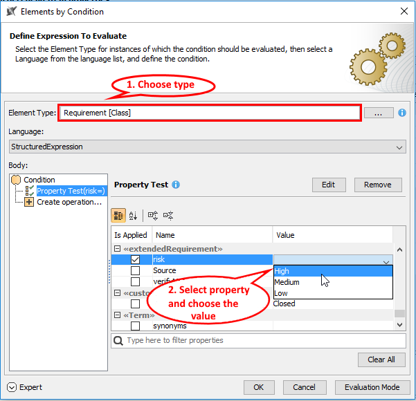
Figure 3. Specifying condition.

A legend item is then applied to all model elements that contain the specified property value.

Jan 122017
 

Creating blocks and defining their ports are one of the most common tasks performed by systems engineers. These elements are reused in the entire model. Therefore, it is very important to maintain the same appearance of the block as defined in a Block Definition diagram, especially when they are used as parts of the system.

MagicDraw has evolved with a unique port layout mechanism. Beginning with MagicDraw version 18.5, this new functionality allows you to keep the same appearance of parts and their ports positions each time you represent them in different diagrams, as illustrated in Figure 1.

Figure 1. Usage of a layout template.

On the left side of Figure 1, the Modem Card block is displayed on the SysML Block Definition diagram (BDD). This diagram is set as a layout template. The defined appearance of the Modem Card block and Male D9 ports (including its positions on that block) can be reused in other diagrams such as a SysML Internal Block Definition Diagram. On the right side of Figure 1, the Modem Card block is used as a part type. The part and its ports are represented identically as in the Modem Card block whose appearance is defined in the layout template diagram.

To utilize the smart port layout and style functionality, follow these steps: define the appearance of the block symbol, set that visual definition as the layout template, and apply the layout template for the particular part. See Figure 2.

port_layout_template_steps

Figure 2. The workflow of setting and applying the ports’ layout template.

Multiple layout templates

Multiple layout templates allow you to represent the same block with a different appearance according to the context where this block will be used. For example, the same USB port position on the Mouse block can be represented in two different ways, as in Figure 3.

multiple_layout_templates

Figure 3. Multiple layout templates.

To do this, you need to define the multiple layout template diagrams with different names that identify the selection (see Figure 3). If you have a commonly used layout template, you can set it as the default.

Layout templates by aspect

Diagram aspects allow you to quickly create different structural views, e.g., electrical, mechanical, optical, for the system structure.

aspect_diagrams

Figure 4. Views through different aspects.

Figure 4, shows three SysML Internal Block diagrams of the same Climate Control Hardware system. Two of them, electrical and communication, are of different aspects. The IBD with electrical aspect shows only the electrical structure of the Climate Control Hardware system, and the IBD with communication aspect shows only those elements that are defined as communication structure elements.

The Block Definition Diagram, when used as a layout template, can have a specific diagram aspect defined. Now, the layout template can only be used in another diagram with the same aspect.

communication-and-electrical-layout-templates

Figure 5. Communication and Electrical layout templates.

In Figure 5, communication and electrical aspects are defined for the Control System Block in two SysML Block Definition diagrams. The same diagrams are also set as layout templates. Now, the Control System with communication aspect and layout template applied can only be used in IBDs with communication aspect as well, as shown in Figure 4. This also applies to the electrical Control System Block.


May 202016
 

The Dependency Matrix is an ideal tool for efficient analysis of dependencies between elements. In some cases, dependencies between particular elements can cause indirect relations with other model elements. Let’s take a look at the following image.

bdd2

In this example above, composition and inheritance structures between blocks are displayed. If a composite part depends on a particular element, the whole element also depends on this element. The same situation exists with inheritance between blocks. Inherited elements indirectly depend on the elements to which a parent element has relations.

Beginning with MagicDraw version 18.3, indirect relations (we call them implied relations), can be displayed on the dependency matrix. Take a look at the following image.

Dependency Matrix

In the preceding example, the High-voltage Battery block satisfies the Plug-In charge requirement. According to the composition and generalization, Power SubSystem and High-voltage Battery Eco blocks should satisfy this requirement as well. These relationships are shown as implied and marked with red dashed arrows.

Moreover, implied relations can be caused not only by generalization and composition. Take a look at the diagram and matrix below:

Capture

In this case, the Category 1 of Ultra Low Emission Vehicle requirement is derived from the Environmentally friendly requirement, which is refined by Provide electric engine power and Provide power from electric and gasoline engines activities. According to this, implied refine relationships between activities and derived requirement are displayed.

To show implied relationships, simply select the Implied Relation operation in the Dependency Criteria dialog and choose needed criteria from the drop -down list as shown here:

Implied relation

Implied relationships can also be used in Relation Maps, Generic Tables, Smart Packages, and Derived Properties.


Mar 042016
 

System designs are created at different levels of abstraction. There are two problems implied by this statement:

  1. A systems engineer working in one abstraction level does not want to use elements from another abstraction level in order to keep the model consistent. For example, when selecting a type of a part property in a SysML model, the engineer only wants to see types from the same abstraction level.
  2. In different abstraction levels, elements may have the same names. So, it takes the user time to find the right one from the desired abstraction level.

Beginning with MagicDraw version 18.3, users can save time to avoid these previously mentioned situations. There are two mechanisms to facilitate custom scope capability.

To improve modeling productivity, users can use Model elements instead of Packages. In this way, element lists are restricted to elements that are owned within the Model element. Here is an example:

Pimport

Fig 1. Model scope

In the example above, when Filter by Package Imports is applied, only the interfaces which are owned in the Physical Model are shown in the type list (marked with the green rectangle). Interfaces nested in another abstraction level – Conceptual Model – are not included in the type list (marked with a red rectangle).

Another way to improve modeling productivity is to model context-specific scopes. All that is needed is to create Package Imports between packages. In this way, lists of types are restricted by imported elements only. Here is an example:

Pimport2

Fig 2. Imported scope

In the example above, a systems engineer uses specific value types from the ISO-80000 library in a specific scope. In another scope, the engineer may choose to use other types, thus improving modeling productivity when there is a need to identify the right types and elements.

Feb 052016
 

Requirements change over time: new requirements are created; existing ones are modified or deleted. Systems engineers need to know the impact these changes will have on other related artifacts such as design elements or test cases. Suspect Links capability helps users track changes in requirements that are linked to design elements, as well as allow tracking disapproved requirements and requirements that are not linked to other elements.

Requirements that have been changed are not marked as suspected. Only elements that are linked to changed requirements are marked as having suspect links. Suspected model elements are highlighted in yellow and marked with a small triangle symbol.

If users are working with a server (CEDW) project, the ability to review changes made in requirements is available. According to these changes, users can update suspected elements and clear that suspicion.

Suspect Links

Suspect Links

This requirements management capability is available beginning with MagicDraw version 18.3. Check what’s new in 18.3 FR