Creating blocks and defining their ports are one of the most common tasks performed by systems engineers. These elements are reused in the entire model. Therefore, it is very important to maintain the same appearance of the block as defined in a Block Definition diagram, especially when they are used as parts of the system.
MagicDraw has evolved with a unique port layout mechanism. Beginning with MagicDraw version 18.5, this new functionality allows you to keep the same appearance of parts and their ports positions each time you represent them in different diagrams, as illustrated in Figure 1.
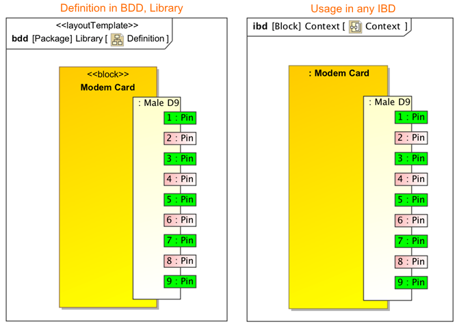
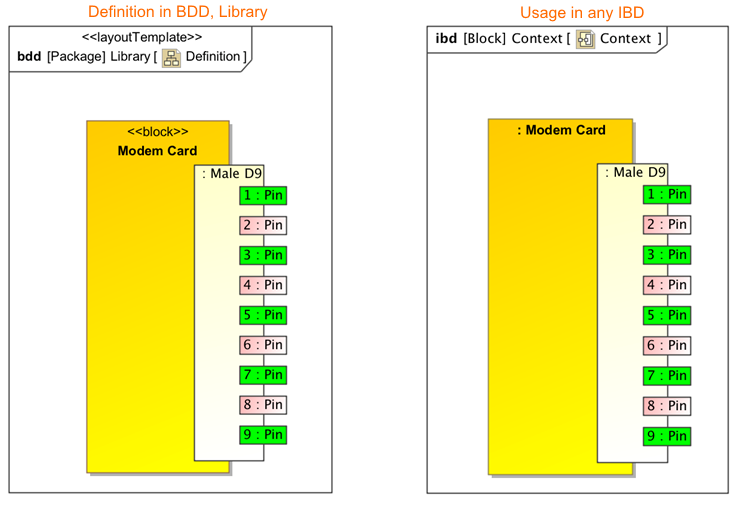
Figure 1. Usage of a layout template.
On the left side of Figure 1, the Modem Card block is displayed on the SysML Block Definition diagram (BDD). This diagram is set as a layout template. The defined appearance of the Modem Card block and Male D9 ports (including its positions on that block) can be reused in other diagrams such as a SysML Internal Block Definition Diagram. On the right side of Figure 1, the Modem Card block is used as a part type. The part and its ports are represented identically as in the Modem Card block whose appearance is defined in the layout template diagram.
To utilize the smart port layout and style functionality, follow these steps: define the appearance of the block symbol, set that visual definition as the layout template, and apply the layout template for the particular part. See Figure 2.
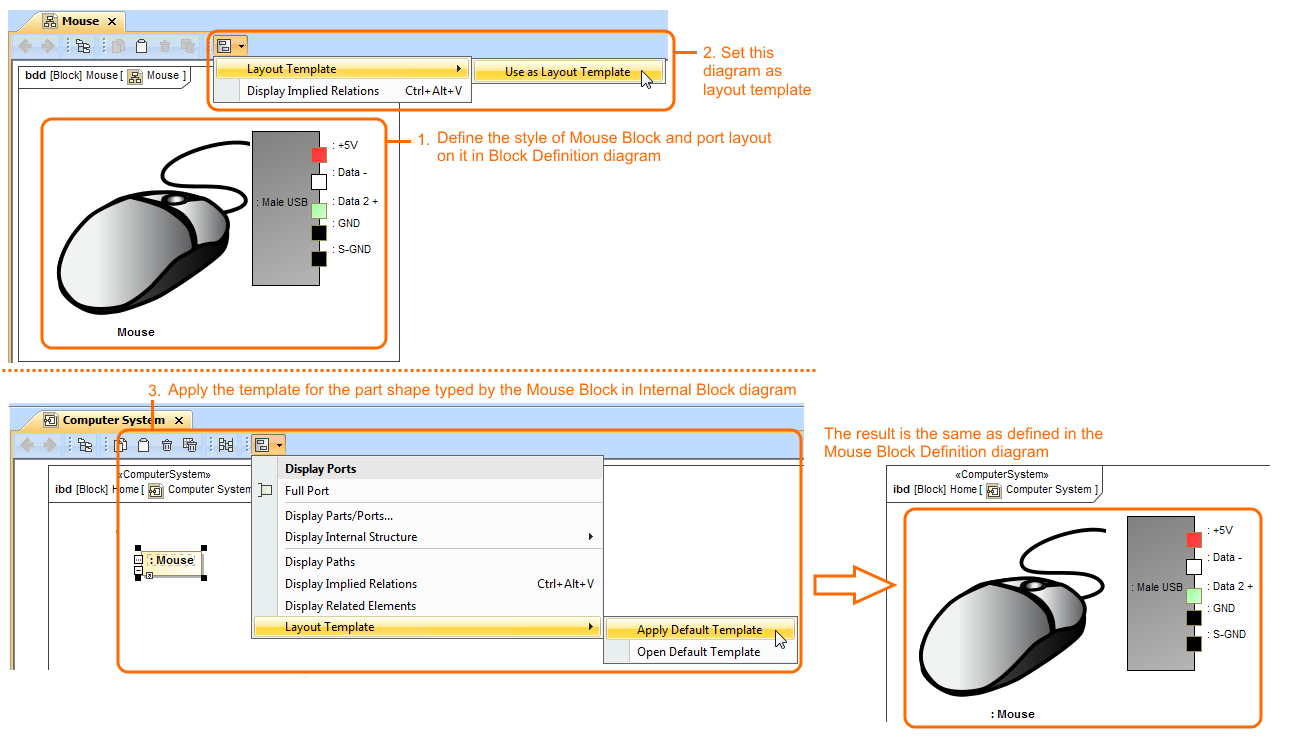
Figure 2. The workflow of setting and applying the ports’ layout template.
Multiple layout templates
Multiple layout templates allow you to represent the same block with a different appearance according to the context where this block will be used. For example, the same USB port position on the Mouse block can be represented in two different ways, as in Figure 3.
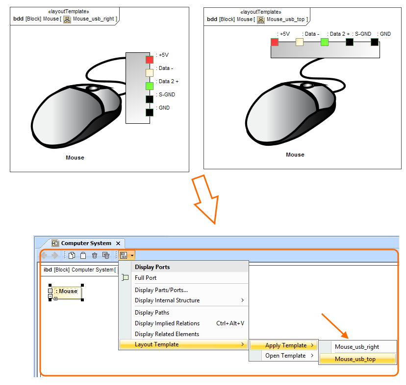
Figure 3. Multiple layout templates.
To do this, you need to define the multiple layout template diagrams with different names that identify the selection (see Figure 3). If you have a commonly used layout template, you can set it as the default.
Layout templates by aspect
Diagram aspects allow you to quickly create different structural views, e.g., electrical, mechanical, optical, for the system structure.
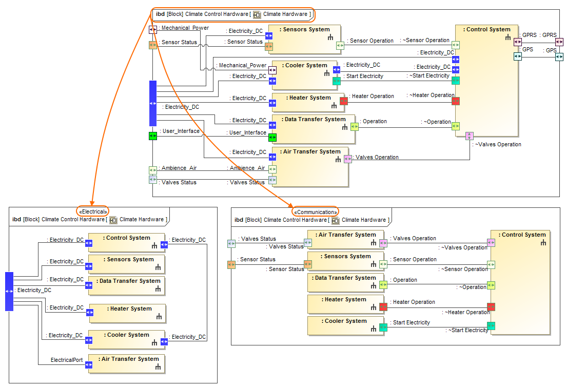
Figure 4. Views through different aspects.
Figure 4, shows three SysML Internal Block diagrams of the same Climate Control Hardware system. Two of them, electrical and communication, are of different aspects. The IBD with electrical aspect shows only the electrical structure of the Climate Control Hardware system, and the IBD with communication aspect shows only those elements that are defined as communication structure elements.
The Block Definition Diagram, when used as a layout template, can have a specific diagram aspect defined. Now, the layout template can only be used in another diagram with the same aspect.
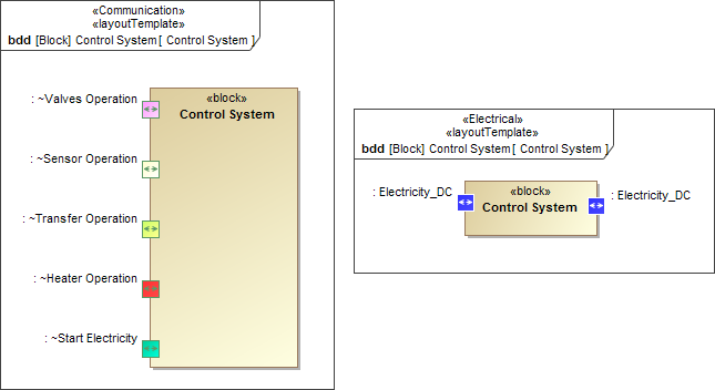
Figure 5. Communication and Electrical layout templates.
In Figure 5, communication and electrical aspects are defined for the Control System Block in two SysML Block Definition diagrams. The same diagrams are also set as layout templates. Now, the Control System with communication aspect and layout template applied can only be used in IBDs with communication aspect as well, as shown in Figure 4. This also applies to the electrical Control System Block.