 This paper shows the use of opaque behaviors containing JavaScripts to enable the communications between the simulated model of the controller and the external device, which is LEGO Mindstorms configured as ShooterBot. The controller model has been designed with MagicDraw SysML plugin and will be executed by Cameo Simulation Toolkit. During model execution, the mock-up panel which is designed with the MagicDraw User Interface Modeling diagram, will open. It provides interface to the user for controlling LEGO Mindstorms to move forward and backward, turn left and right, and fire balls.
1. Introduction
1.1 Overview
Model-driven simulation currently receives much attention from research communities and industries. It can help system engineers gain more understanding about the designed system without manipulating the real system, which may be due to the fact that it is not yet defined or available, or it cannot be exercised directly owing to cost, time, resources, or risk constraints.
Cameo Simulation Toolkit is the extension of MagicDraw which provides an extendable model execution framework based on OMG fUML [1] and W3C SCXML standards. It extends MagicDraw to validate system behavior by executing, animating, and debugging UML state-machines and activity models in the context of realistic mock-ups of the intended user interface.
The opaque behavior is one of the UML elements that can be executed by Cameo Simulation Toolkit. When the Cameo Simulation Toolkit executes the opaque behavior, the script contained in the opaque behavior will be executed if it is written in any language supported by JSR-223 (Scripting for the Java Platform). This ability can be used to enable communication between the simulated model and external system. It can be applied to create a system operated by the collaboration between the simulated model and the external devices. For example, in the controller’s system, the controller modeled with MagicDraw SysML can control the external devices through Cameo Simulation Toolkit. LEGO Mindstorms is the external device that we are interested in.
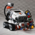
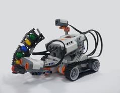
LEGO Mindstorms contains software and hardware to create a customizable and programmable robot. LEGO Mindstorms NXT 2.0 is the version deployed in this project. This version contains 3 motors, 1 Ultrasonic sensor, 1 LED and light sensor, 2 touch sensors, and 1 brick processing unit. However, this project does not use touch sensors.
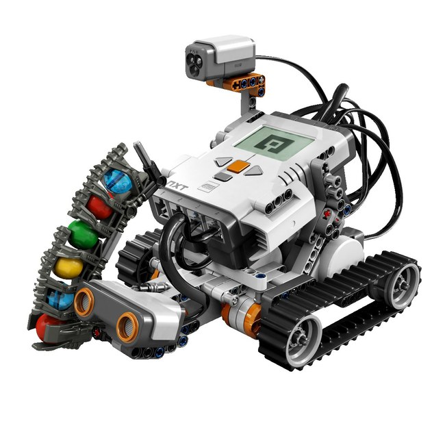
Figure 1 – LEGO Mindstorms
1.2 Objective
In this work, the model of LEGO Mindstorms and its controller will be created with MagicDraw SysML, whereas Cameo Simulation Toolkit will be used to execute the designed model. The control signals, including moving forward and backward, turning left and right, and firing balls, will be sent out to control the real LEGO Mindstorms using opaque behaviors which contain JavaScript.
2. System Requirements
MagicDraw UML v17.0.2 with SysML plugin v17.0.2 and Cameo Simulation Toolkit v17.0.2 are the tools used for designing and simulating the models of both the controller and the LEGO Mindstorms on Microsoft Windows XP. The simulated model will send out control signals to control the real LEGO Mindstorms device through Bluetooth and USB cable.
2.1 LEGO Mindstorms
In this work, we use the LEGO Mindstorms NXT 2.0. It will be configured using a simple pattern called “Shooterbot,”
a simple mobile robot with a ball shooter and ultrasonic and color sensors as shown in Figure 1. The building instruction can be found in the LEGO Mindstorms NXT User Guide [2].
2.2 leJOS NXJ Library
The leJOS NXJ Library [3] is a Java programming environment for LEGO Mindstorms. It allows the user to program LEGO Mindstorms in Java. leJOS NXJ library provides an API for controlling the robots and also provides replacement firmware that includes a Java Virtual Machine for the LEGO Mindstorms. Therefore, the original firmware must be replaced with it. The version of leJOS NXJ Library used in this work is 0.9.1 for Microsoft Windows platform. The leJOS NXJ Library and its information can be found at http://lejos.sourceforge.net/.
2.3 NXT Library Plugin for MagicDraw
NXT Library plugin is a MagicDraw plugin developed in this work. It opens the connection between MagicDraw and LEGO Mindstorms through leJOS NXJ Library. Mainly, it has been created to maintain the NXTConnection object of leJOS NXJ Library. The NXTConnection object must be created to enable the connection between MagicDraw and LEGO Mindstorms. If the NXTConnection object is instantiated within the JavaScript contained in the opaque behavior, it will be destroyed immediately after the opaque behavior has been executed by Cameo Simulation Toolkit v17.0.2. Therefore, the NXTConnection must be initiated in every opaque behavior in such case.
Not only maintaining the NXTConnection object, but the NXT Library Plugin for MagicDraw, provides utility functions which can be easy called by JavaScript contained in the opaque behaviors. These utility functions are:
-
LEGO connection functions via Bluetooth or USB cable.
-
Motor functions for controlling the motor rotator spinning clockwise or counterclockwise.
-
LED-light function for turning the specified color of LED on or off.
-
Ultrasonic sensor function for detecting the nearest object.
-
ShooterBot motion control functions for controlling the robot to move forward and backward and turn left and right.
3. System Model
MagicDraw with SysML plugin is the tool selected for modeling the system. The designed system can be separated into four parts: NXT model library, Controller model, ShooterBot model, and the UltrasonicSensor model as shown in Figure 2.
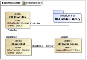
Figure 2 – Packages and the SysML Blocks of the Designed System
3.1 NXT Model Library
NXT Model Library is a UML model consisting of a set of pre-defined opaque behaviors. These opaque behaviors contain JavaScript calling the Java methods provided by NXT Library plugin for MagicDraw.
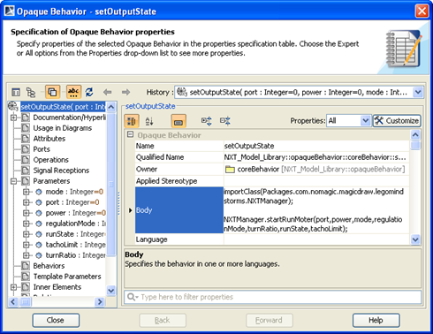
Figure 3 – Opaque Behavior for Setting the Output State of the Motor
They can be reused to model complex activities by creating call behavior actions calling opaque behaviors as shown in Figure 4. The SysML Activity diagram represents the opaque behaviors that move the robot forward by using call behavior actions calling setOutputState, which is an opaque behavior containing JavaScript calls for the NXT Library plugin for MagicDraw.
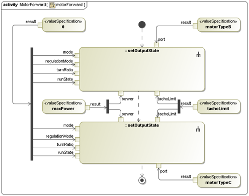
Figure 4 – Activity Diagram of motorForward Opaque Behavior
3.2 Controller Model
The controller is the system for sending control signals to the ShooterBot. Here, it is represented by the NXT Controller block. Its behaviors are defined with state machines and activities of such block. The classifier behavior of the NXT Controller block is modeled with SysML state-machine diagram shown in Figure 5. The controller will change its state when it receives a triggered signal indicated on a transition. Each state may have a specified entry and/or exit activity which will be performed by Cameo Simulation Toolkit when the execution enters or exits the state.
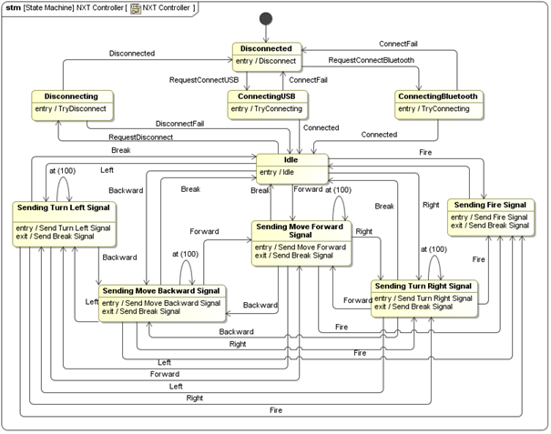
Figure 5 – Controller’s State Machine
For example, in Figure 5, if the controller receives the Fire signal when the controller is in the Idle state, the controller’s state will be changed from the Idle state to Sending Fire Signal state, and the Send Fire Signal activity, as the entry activity of the Sending Fire Signal state, is executed. The actions which will be performed by the Send Fire Signal activity are described by the SysML Activity Diagram shown in Figure 6.
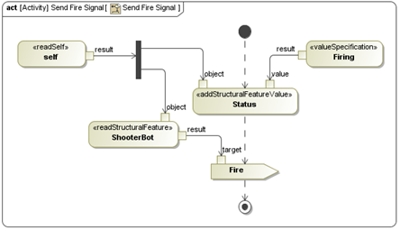
Figure 6 – SysML Activity Diagram of the Send Fire Signal Activity
When the Send Fire Signal activity is executed, the status of the controller will be changed to “Firing,” and then the Fire signal will be sent from controller to ShooterBot.
To create a user interface for the controller, we use the MagicDraw user interface diagram. With Cameo Simulation Toolkit, when a signal is dragged to the UI frame element, a button for sending the dragged signal will be created. When the button is clicked, the signal will be sent to the controller and trigger the controller to change the state. Figure 7 shows the user interface of the controller created. The dialog represents the NXT Controller block. It consists of buttons for sending signals specified by the labels on the buttons. The Status label represents the value of the Status property of the NXT Controller block. Nearest Object in the Sensor group box is the label representing the value of the NearestObject property of Sensor of the NXT Controller block. This value is the distance between ShooterBot and the nearest object detected by the ultrasonic sensor.
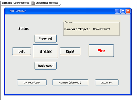
Figure 7 – Controller’s User Interface
3.3 ShooterBot Model
The ShooterBot model is similar to the controller’s model. The ShooterBot block represents ShooterBot. It consists of state machines and activities of ShooterBot. The classifier behavior of the ShooterBot block is defined by the ShooterBot state machine shown in Figure 8. The ShooterBot block is set to the active block (IsActive = true). Thus, its classifier behavior will automatically start when the ShooterBot runtime object is created.
During model execution, the runtime object of ShooterBot receives control signals sent from the controller. They will trigger the ShooterBot runtime object to change the state. Then, the activities specified at the entry and the exit of states will be executed. The executed activities have call behavior actions calling the opaque behaviors defined in NXT library. Thus, the control commands can be sent to control the real ShooterBot.
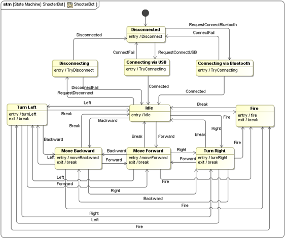
Figure 8 – State Machine for Movement and the Firing System of ShooterBot
For example, When ShooterBot is connected to the controller, it will be in the Idle state. If it receives the Fire signal sent from the controller, the Fire activity of ShooterBot, described by SysML Activity Diagram in Figure 9, will be executed. The red LED will be turned on. After that, all motors will stop, and the balls will be fired by spinning the rotator of motor A.
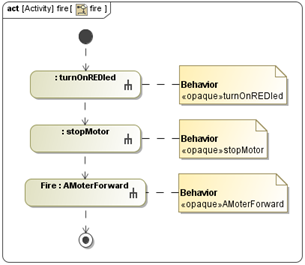
Figure 9 – SysML Activity Diagram for Firing the ShooterBot Action
The SysML Activity diagram shown in Figure 8 shows the using of call behavior actions typed by opaque behaviors defined in NXT model library. The JavaScript contained in the opaque behaviors will be executed when the call behavior actions is activated by Cameo Simulation Toolkit.
3.4 Ultrasonic Sensor Model
The ultrasonic sensor model detects the distance between the ShooterBot and the nearest object. The UltrasonicSensor block represents the ultrasonic sensor. It has an Ultrasonic Sensor state machine specified as its classifier behavior. The Ultrasonic Sensor state machine is described by SysML State Machine diagram as shown in Figure 10.
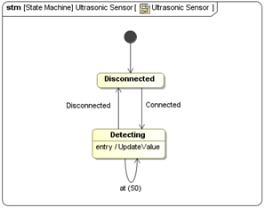
Figure 10 – SysML State Machine Diagram of Ultrasonic Sensor State Machine
In this model, UltrasonicSensor updates the distance between ShooterBot and the detected object every 50 millisecond by calling the UpdateValue actvity as indicated in Figure 11.
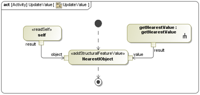
Figure 11 – SysML Activity Diagram of the UpdateValue Activity
4. Execution Result
After the model of ShooterBot, UltrasonicSensor, and NXT Controller models have been completed, the execution configuration and the instance specification of the models must be created with specified values. They will be executed with Cameo Simulation Toolkit. To execute the models, their instance specification must be created with the values specified as shown in Figure 12.

Figure 12 – InstanceSpecification with Specified Values
For the Execution Configuration element, it will be created with the specified properties values shown in Figure 13. The execution target of the execution configuration is the instance specification of NXT Controller.

Figure 13 – Specification Dialog of Execution Configuration
The created execution configuration will be selected and executed by Cameo Simulation Toolkit. The mock-up panel, designed with the MagicDraw User Interface Modeling diagram, will be displayed as shown in Figure 14.
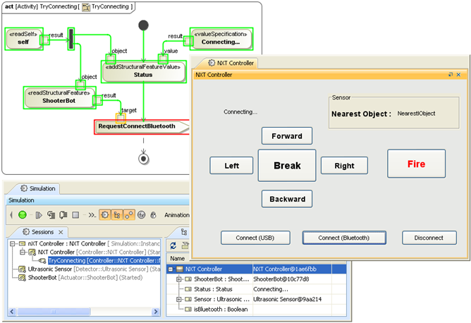
Figure 14 – Model Execution and the Mock-up Panel
When the button in the mock-up panel is clicked, the signal associated with the button can be sent out to control ShooterBot. The status of the system and the distance between ShooterBot and the detected object will be shown in the mock-up panel.
5. Conclusion
This work shows the system operated by the collaboration between the simulated model in Cameo Simulation Toolkit and external devices represented by LEGO Mindstorms. The NXT Model Library has been created as a MagicDraw model library. It has pre-defined opaque behaviors containing JavaScripts, calling the NXT Library plugin for MagicDraw. The leJOS NXJ Library enables communications between the plugin and the real LEGO Mindstorms. The controller’s system has been modeled with MagicDraw SysML. It has activities that use call behavior actions calling the opaque behaviors in NXT Model Library, for sending the control signals to LEGO Mindstorms.
In simulation, the simulated model of the controller can be used to control the real LEGO Minstroms. The mock-up user interface, modeled by MagicDraw User Interface Modeling, allows the user to select buttons to control the robot to move forward and backward, turn left and right, and fire the balls.
The concept of using opaque behaviors with specified JavaScripts to enable communication between the simulated model and the external system can be applied to many engineering applications, especially to control applications where the controller modeled can be readily used without the need of manipulation of the real systems. It can effectively help engineers reduce cost, time, and resources in the development of new systems.
6. Prototype
This prototype uses leJOS NXT Library. It can be used with 32-bit Java Runtime Environment only. Therefore, you have to use 32-bit Java Runtime Environment to run MagicDraw and Cameo Simulation Toolkits.
The original prototype for the Cameo Simulation Toolkit v17.0.2 can be downloaded here.
The updated version of LEGO Mindstorm plugin for Cameo Simulation Toolkit v18.0 beta can be downloaded at LegoMindstorm_Plugin_v18.0beta
7. References
- Semantics of a Foundational Subset for Executable UML Models (fUML), v1.0, OMG, http://www.omg.org/spec/FUML/1.0/ [Online]
-
LEGO MINDSTORMS User Guide: Mindstorms NXT 2.0 Build and Program Robots That Do What You Want!, The LEGO Group.
-
The leJOS NXJ Tutorial, http://lejos.sourceforge.net/nxt/nxj/tutorial/ [Online].
8. Credits
The case and prototype for Cameo Simulation Toolkit v17.0.2 was made by:
- Kampanath Panthithosanyu (kampanath_p@nomagicasia.com)
- Jirawat Lakomnouyporn (jirawat_l@nomagicasia.com)
- Wachira Manasmeteekul (wachira_m@nomagicasia.com)
- Kritsana Uttamang, PhD (kritsana_u@nomagicasia.com)