
Aurelijus Morkevičius

Avatar

I am Solution architect @ No Magic for model-based systems and software engineering (mostly based on SysML and UML) and defense architectures (DoDAF, MODAF, NAF). I'm Working with companies such as General Electric, Kongsberg Defense and Airspace, INDRA, ESS, Amadeus, BMW, etc. I hold PhD in Informatics Engineering.

Apr 092015
 

UAFA wind of changes blew two weeks ago in the OMG meeting in Reston deciding the future of Unified Profile for DoDAF and MODAF (UPDM). There were a lot of talks about OMG taking over DoDAF and renaming it to UAF; however that is not exactly the truth. DoDAF is here and OMG is not going to change it. A brand new UAF is a new framework 100% compatible with DoDAF, MODAF, NAF etc. What does it mean? You remember the Zachman framework? It is similar. It is an abstract framework supporting all the more specific frameworks mentioned above and at the same time providing a configurable platform to build industrial enterprise architectures. Platform means all of it: viewpoints, aspects, meta-model, and profile (UAFP).

So let me introduce what actually happened during the week in Reston.

MBSE and UAF information day

It all started from the special event called “MBSE and UAF information day”. This is the event organized by the OMG UPDM working group with the help of the OMG guys. There was a lot in the press regarding it, e.g. finance.yahoo.com, www.businesswire.com, www.reuters.com, etc. Just look for “MBSE and UAF information day.” The official site for the event is: http://www.omg.org/news/meetings/tc/va-15/special-events/UAF_MBSE_Day.htm.

Basically it had two major goals:

  • Introduce defense people to UPDM, its adoption and future needs.
  • Get support from DoD to continue our work towards UAF

Rory Kinney, Director for Architecture and Engineering, gave the keynote; his support for UAFP is more than important. The second presentation was the UPDM co-chairs presentation where every co-chair got a 10 minutes slot to explain the past, present and future of UPDM. Then Steve W. Mitchell, LM Fellow, Master Architect, INCOSE ESEP, Lockheed Martin spoke. I give credit to his very well done briefing. Then Lars-Olof Kihlström, Principal Consultant, Syntell AB and Paul Vaughan, NGIS Tech Fellow, EPS CAPS Chief Engineer and Architect, Northrop Grumman, spoke. The event was closed by Philomena (Phil) Zimmerman, Deputy Director, Engineering Tools and Environments ODASD(SE)/EE.

All the presentations are available to download in the official event website at http://www.omg.org/news/meetings/tc/va-15/special-events/UAF_MBSE_Day.htm.

Unified Profile for DoDAF and MODAF Workshop

The MBSE and UAF information day was followed by the Unified Profile for DoDAF and MODAF Workshop sponsored by No Magic. It was a follow-up on the morning session providing more detailed information about UPDM applications. The official site for the event is: http://www.omg.org/news/meetings/tc/va-15/special-events/No_Magic_Info_Day.htm

I did the first talk on UPDM benefits, emphasizing the importance of UPDM being a part of OMG standards family. The presentation explains the benefits of UPDM, plus the benefits from the modeling tool, Cameo Enterprise Architecture in particular. Please find my presentation attached:

Download (PDF, Unknown)

The No Magic CTO, Kent Laursen, did the presentation on the use of UPDM for DoD Programs and Architectures. The event was closed by our partner, Nikolai Mansourov, Chief Technical Officer, KDM Analytics. His presentation was about Cameo Risk Manager. It is a new tool that analyses the XMI file produced by UPDM modeling tool, allows the user to set some additional properties on parsed UPDM entities, build fault trees and perform risk assurance analysis. More information on the tool is available at: http://www.nomagic.com/products/cameo-risk-manager.html

Rest of the week

By getting the green light from UPDM stakeholders, the UPDM group started working on the new standard. It is obvious now there are going to be two specifications in the future one called UAF 1.0 and the other UAFP 1.0. UAF will contain a new Grid approach structuring views and viewpoints and the meta-model. UAFP will contain a UML profile for UAF. One thing is obvious, the target customer for a new framework has changed – industrialization of UPDM has just started. We will see what happens in the close future as the deadline for specification release is set to the first half of 2017.

Sincerely,

Dr. Aurelijus Morkevicius

Co-chair UAF
Nov 202014
 

Model Based Systems Engineering (MBSE) promises an increase in productivity by shifting from documents to models as the main means to develop systems. However, in order to reach this promise, an organization has to implement proper standardized practices, which enables productive analysis on models. Organizations not complying with the standardized approach suffer from the loss of capability to inter-exchange and communicate with other teams, overhead in tool customization, and specific training needs. Moreover, the models become impossible to integrate and reuse.

MBSE in most of the cases is followed by Systems Modeling Language (SysML); however, in just a few of them, a complete set of benefits, the language and the modeling tool provides, are exploited. Have you ever heard of fUML, SCXML, and SysML parametric analysis? These are powerful standardized techniques to perform engineering analysis on models. Have you ever thought using them all together? This combination can be even more powerful tool to solve complex systems engineering tasks and this is exactly what this session is all about.

The session demonstrates:

  • State Machines execution
  • Activities execution
  • Action Language Helper
  • SysML parametric execution
  • Integration with external math engine, in particular MATLAB
  • Combined model execution
  • Building executable user interface

The session was hosted by Dr. Aurelijus Morkevicius, Senior Solution Architect at No Magic, Inc.

Learn more at: http://www.nomagic.com/mbse/

Jul 042014
 

Perform advanced Numeric Computations with values in the SysML model.

Analyze and Visualize SysML model data.

Set-up Co-simulation.

Cameo Systems Modeler provides multiple integration points with the most popular environments for numerical computation, visualization, and programming – such as  Mathworks MATLAB, Wolfram Mathematica, and Maple, including:

Direct functions calling

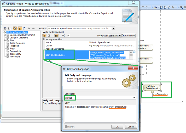
Math solver functions can be called directly from SysML Activity diagrams using Opaque actions. Script, referring by name, can access all variables in the particular context, such as value properties of the enclosing block, activity parameters, and input pins.

FunctionCall

Figure 1. Function call


Invoking Simulink model (MATLAB specific)

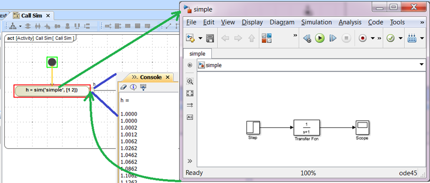
Use “sim” function to invoke Simulink model.

Fig. 2 Invoke Simulink model

Figure 2. Invoking Simulink model


Math Engine as parametric solver

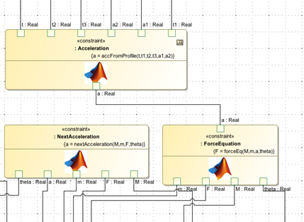
Use Math solver to solve SysML Parametric model, featuring acausal solving of parametric equations.

Solver

Figure 3. Parametric solver


Command line

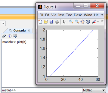
Type and execute Math solver functions directly in Cameo Systems Modeler and directly at run-time.

CommandLine

Figure 4. Command line


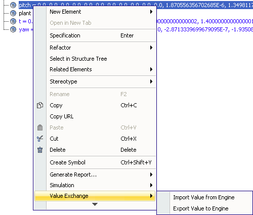
Import/Export run-time variables

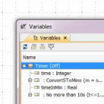
Exchange workspace variables in Math solver with values of the SysML model.

Variables

Figure 5. Variables


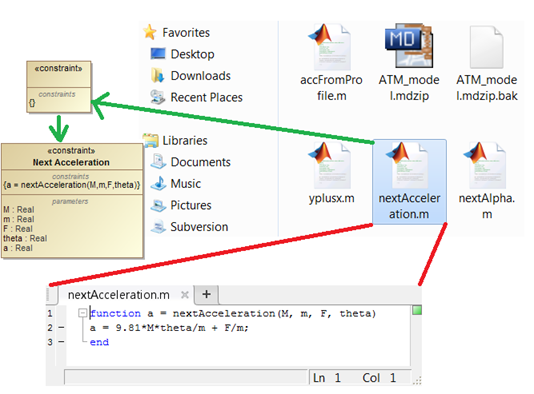
Parse M-files (MATLAB specific)

Drag & Drop M-file onto Cameo Systems Modeler and you’ll get it parsed and SysML Parametric Equation created and populated with parameters.

Parser

Figure 6. M-files parser


Remote solver support

Connect to Math solver server deployed anywhere in the world.

Jan 202014
 

SysML defines neither an architecture framework nor a method. This opens discussions of how to structure the model, what views to build, which artifacts to deliver and in what sequence. Every customer I see deals with the same issue a bit differently. Some use defense architecture frameworks like DoDAF, NAF, MODAF, others use FAS; however, saying there is no need for an architectural framework just doesn’t work. You always end-up using an architecture framework whether you want one or not, or whether you intend to or not.

When analyzing available alternatives, the defense frameworks are considered to be heavyweight, although they do not require using a full set of views, and FAS is not as well-known and or used yet. Option number three is to define your own custom architectural framework (AF). This is what usually happens in reality. There are so many domains in system engineering; it is no wonder the approach for designing different types of systems differs.

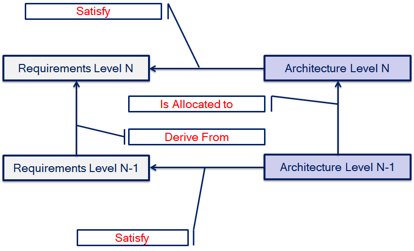
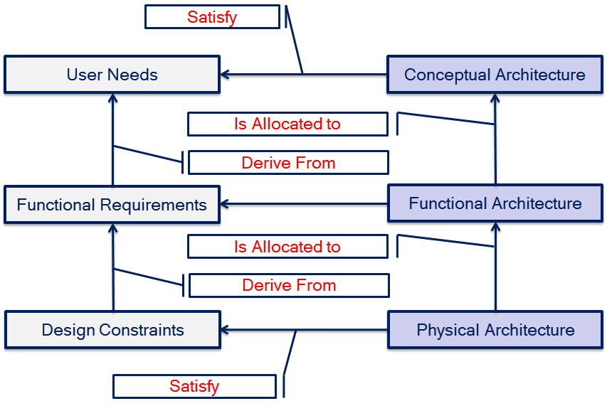
In this post, I, being a part of such framework developments in various organizations, defined a pattern (Magic Pattern) for a custom AF based on SysML (see figure 1).

Magic Pattern

Figure 1. Magic Pattern

One client argued that instead of derivation he would use refinement. So go ahead, I said, it is not against SysML. SysML provides a set of elements; however, it is up to you to interpret their usage in most of cases.

An example of the pattern shown in figure 1 could be a framework consisting of three levels of abstraction (see figure 2):

1. Conceptual – defines the core concepts of the system context and their interactions. The undoubted benefit of views created in the conceptual model is sharing core concepts of the system context between stakeholders.
2. Functional – defines functional analysis from the behavioral perspective, where functions instead of structural units are emphasized. Do not mix this up with the Logical architecture. They are different; however, explaining the difference requires another post.
3. Physical – defines equipment, their physical interfaces and parameters. The physical model is usually a subject for simulation and model-based testing.

Example of Magic Pattern

Figure 2. Example of Magic Pattern

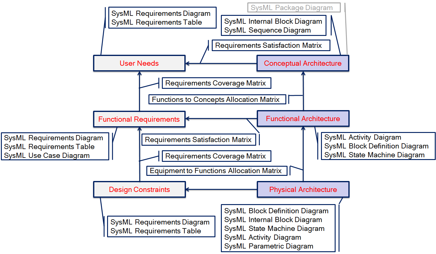
Figure 2 shows a single possible instance of Magic Pattern shown in figure 1. Each of the architecture models and relationships among them can be represented in SysML using a different set of elements and views (diagrams, matrices, tables, etc.). E.g. functional requirements can be depicted in SysML Requirements Diagram or SysML Requirements Table; conceptual architecture can be depicted in IBD (see my blog post on  Conceptual Models in SysML), Use Case diagram, Sequence Diagram etc. See figure 3 for my recommendations.

Diagrams

Figure 3. Architectural Models to SysML Diagrams Mapping

As you can see in the figure 3, the SysML Package Diagram is marked in Grey. This is because it can be created in any architecture model or can be skipped. The purpose of this diagram is to organize the model, thus generally it is created at the beginning and updated afterwards.

The SysML Use Case Diagram is sometimes used to define User Needs. There is a concept of Business Use Case used for such purpose.

Relationships between architecture models are derived from the relationships between model elements, e.g. functional requirement derivation from some user need implies the dependency of the functional requirements model from the user needs model.

Summarizing, it can be clearly seen that there are so many variations of architectures, models, diagrams and combinations of them (note that we have not touched the process yet), that crafting a custom architectural framework is not an easy task. For this reason I will look into use of defense architecture frameworks with SysML in my upcoming post. In my future posts I will also provide some best practice tips and examples for each of the architecture models.


Jan 172014
 

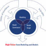
The traditional document-centric systems engineering paradigm is currently under slow transition to model-based systems engineering (MBSE) approach. There are many reasons for the slowness of this transition. For instance, there are many long-term projects, rumors about unsuccessful applications of MBSE, too little information available how to proceed, disbelief, etc. However, the core barrier is definitely a cultural change. A journey to MBSE is long, and companies adopting it need guidance to help make paradigm shift rewarding. The first and the most important step in shifting to MBSE is to adopt sustainable modeling culture in the organization. I define modeling culture as a combination of modeling, model usage, and model governance, that together provides a productive way for applying model-driven development in the context of a particular organization. Only if modeling culture is successfully adopted can you can expect high value from MBSE. So: How to Build a Sustainable Modeling Culture?

The answer is simple:

Learn from the mistakes of others – Talk with professionals before you get going.

Think big, start small, and evolve – A good example is to at least build a proof of concept model before applying MBSE on a real project. It is a long process to adopt MBSE. The core mistake at the beginning is that people overestimate their abilities in the field of modeling. Knowing SysML, for instance, is at most 5% of what you need to know in order to be successful in MBSE.

Establish a Center of Excellence – An MBSE initiative needs to be coordinated by experienced system engineers in combination with modeling experts, presumably the group of people driving the MBSE initiative in the organization.

Adopt best practices – for this and all points above refer to the slides I presented at multiple conferences (NOSE 2013, Hamburg, Copenhagen, Stockholm; ICIST 2013, Kaunas):