How modeling can be useful to better define and trace requirements
In this paper, we will show how the SysML modeling language can be useful to complement the requirements process, i.e. to better define and trace requirements. The Systems Modeling Language (SysML: www.omgsysml.org) is a general-purpose graphical modeling language, defined by the Object Management Group (OMG), based on the well-known Unified Modeling Language (UML: www.uml.org). It is used for specifying, analyzing, designing and verifying complex systems, and is designed to provide simple but powerful constructs for modeling a wide range of systems engineering problems. It is particularly effective in specifying requirements: the structure, behavior, allocations and constraints on system properties that support engineering analysis.
This article will explore in depth the specific constructs proposed by SysML (as compared to UML) to model both requirements and traceability. We will see how the Requirement diagram enables the capture of requirements hierarchies and derivations, and how the “satisfy” and “verify” relationships allow a modeler to relate a requirement to either a design element that satisfies it or a test case that verifies it. We will also give practical recommendations on how to best use these particular modeling constructs.
1. What is SysML?
1. Origins of SysML
In all domains, those building complex systems have already been modelling for a long time:
- to harness complexity
- to reduce risks
- to communicate.
SysML™ is a general-purpose graphical modeling language for specifying, analyzing, designing and verifying complex systems that may include hardware, software, information, personnel, procedures and facilities. It is a specialized UML profile targeted to system engineering.
To visualize the relationship between the UML and SysML languages, consider the Venn diagram shown in Figure 1, where the sets of language constructs that comprise the languages are shown as the circles marked “UML” and “SysML” respectively. The intersection of the two circles, shown by the region marked “UML reused by SysML”, indicates the UML modeling constructs that SysML reuses. The region marked “SysML extensions to UML” in Figure 1 indicates the new modeling constructs defined for SysML that have no counterparts in UML, or which replace UML constructs. Note that there is also a part of UML that is not required to implement SysML, which is shown by the region marked “UML not required by SysML”.
![Figure 1: Relationship between SysML and UML – from <sup><a id="a-2" title="Reference" href="#fn-2">[OMG1]</a></sup>](https://re-magazine.ireb.org/content/01-issues/06-2015-2-bridging-the-impossible/05-modeling-requirements-with-sysml/grafik-sysml-1.svg "Figure 1: Relationship between SysML and UML – from <sup><a id=\"a-2\" title=\"Reference\" href=\"#fn-2\">[OMG1]</a></sup>")
2. SysML Diagram Types
The nine SysML diagram types are identified in Figure 2 (white boxes) and summarized below.
![Figure 2: SysML Diagram Types – from <sup><a id="a-3" title="Reference" href="#fn-3">[OMG2]</a></sup>](https://re-magazine.ireb.org/content/01-issues/06-2015-2-bridging-the-impossible/05-modeling-requirements-with-sysml/grafik-sysml-2.svg "Figure 2: SysML Diagram Types – from <sup><a id=\"a-3\" title=\"Reference\" href=\"#fn-3\">[OMG2]</a></sup>")
The behavior diagrams include the use case diagram, activity diagram, sequence diagram and state machine diagram. A use case diagram provides a high-level description of functionality that is achieved through interaction among systems or system parts. The activity diagram represents the flow of data and control between activities. A sequence diagram represents the interaction between collaborating parts of a system. The state machine diagram describes the state transitions and actions that a system or its parts perform in response to events.
The system structure is represented by block definition diagrams and internal block diagrams. A block definition diagram describes the system hierarchy and system/component classifications. The internal block diagram describes the internal structure of a system in terms of its parts, ports and connectors. The package diagram is used to organize the model. The parametric diagram represents constraints on system property values such as performance, reliability and mass properties, and serves as a means to integrate the specification and design models with engineering analysis models.
SysML includes a graphical construct to represent text-based requirements and relate them to other model elements. The requirement diagram and all its associated concepts will be detailed in the next chapter. For more information about SysML, a useful reference is [FMS].
2. SysML new constructs for modeling text-based requirements
SysML defines specific elements for modeling requirements and their relationships which did not exist in the more well-known UML. It also includes relationships to other artifacts such as test cases or design blocks, for traceability purposes.
All these constructs will be explained in detail in the following paragraphs.
1. Requirement concept in SysML
Let us quote the SysML Specification [OMG3]: “A requirement specifies a capability or condition that must (or should) be satisfied. A requirement may specify a function that a system must perform or a performance condition a system must achieve”.
Use cases (which existed in UML) are effective for capturing the functional requirements, but not suitable for expressing non-functional requirements. The incorporation of text-based requirements into SysML effectively accommodates a broad range of requirements.
Standard SysML Requirement
A standard SysML requirement includes properties to specify its unique identifier and text requirement itself, as shown in figure 3. Additional properties such as verification status, priority, etc., can also be specified by the user.

Requirement Subclasses
Modelers can customize requirements taxonomies by defining additional subclasses of the Requirement stereotype. For example, a modeler may want to define requirements categories to represent operational, functional, interface, performance, physical, storage, activation/deactivation, design constraints and other specialized requirements such as reliability and maintainability, or to represent a high level stakeholder need. The stereotype enables the modeler to add constraints that restrict the types of model elements that may be assigned to satisfy the requirement. For example, a functional requirement may be constrained so that it can only be satisfied by a SysML behavior such as an activity, state machine or interaction.
Requirement Packages
Requirements can be organized into a package structure. A typical structure may include a top-level package for all requirements. Each nested package within this top-level package may contain requirements from different specifications (system, subsystem, component, etc.). Each specification package contains the text-based requirements for that specification. This package structure corresponds to a typical specification tree, which is a useful artifact for describing the scope of requirements for a project.
2. Requirement Relationships
Capturing requirements in your system model is useful. However, the greater value lies in the relationships you create among the requirements and other model elements.
Seven requirements relationships are specified that enable the modeler to relate requirements to one another as well as to other model elements. These include relationships for defining a requirements hierarchy, deriving requirements, satisfying requirements, verifying requirements and refining requirements. However, the semantics of these relations are not defined in a formal sense and are subject to interpretation. Therefore it is necessary to define some kind of heuristics, guidelines and practices as to how these relationships should be used in order to have a consistent model.
All available relationships in SysML will be explained in detail in the next paragraphs.
Containment (Composite Requirement)
A Composite Requirement can contain sub-requirements in terms of a requirements hierarchy, specified using the namespace containment mechanism. A composite requirement may state that the system shall do A and B, which can be decomposed into the child requirements that the system shall do A, and the system shall do B (as shown in figure 4).

The partitioning of composite requirements into simpler requirements helps establish full traceability and show how individual requirements are the basis for further derivation, as well as how they are satisfied and verified.
Derive Relationship
Derived requirements generally correspond to requirements at the next level of the system hierarchy. A simple example would be a vehicle acceleration requirement that is analyzed to derive requirements for engine power, etc., as shown in figure 5.

It is also used to represent a relationship between requirements at the same level of the hierarchy but at different levels of abstraction. For example, the hardware or software requirements that are originally specified by the systems engineering team may be analyzed by the hardware or software team to derive more detailed requirements that reflect additional implementation considerations or constraints. The more detailed requirements from the hardware or the software team may be related to the original requirements, specified by the system team, through derive relationships.
Refine Relationship
The refine requirement relationship can be used to describe how a model element, or set of elements, can be used to further refine a requirement. For example, a use case or activity diagram may be used to refine a text-based functional requirement, as shown in figure 6. Alternatively, it may be used to show how a text-based requirement refines a model element. In this case, some elaborated text could be used to refine a less fine-grained model element.

A refinement should clarify the requirement’s meaning or context. It is distinguished from a derive relationship in that a refine relationship can exist between a requirement and any other model element, whereas a derive relationship can only exist between requirements. In addition, a derive relationship is intended to impose additional constraints based on analysis.
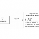
Satisfy Relationship
The satisfy relationship describes how a design or implementation model concept satisfies one or more requirements. A system modeler can then specify the system design elements that are intended to satisfy the requirement, as shown in figure 7.

An important point, however, is that an assertion does not constitute proof. The satisfy relationship is simply a mechanism to allocate a requirement to a structure. The proof that the requirement has indeed been satisfied will come from test cases (see next paragraph).
Verify Relationship
The verify relationship defines how a test case or other model element verifies a requirement, as shown in figure 8. In SysML, a test case or other named element can be used as a general mechanism to represent any of the standard verification methods for inspection, analysis, demonstration or test.

Copy Relationship
There is a real need for requirement reuse across product families and projects. Typical scenarios are regulatory, statutory or contractual requirements that are applicable across products and/or projects and requirements that are reused across product families.
SysML introduces the concept of a slave requirement, as shown in figure 9.

The text property of the copied requirement is a read-only copy of the text property of the source requirement, but the copied requirement has a different id and may be contained in a different namespace.
Trace Relationship
A generic trace requirement relationship provides a general-purpose relationship between a requirement and any other model element, as shown in figure 10. The semantics of trace include no real constraints and are therefore quite weak. As a result, I usually recommend that you instead use one of the other (more meaningful) requirements relationships presented before.

However, the trace relationship can be useful for relating requirements to source documentation or for establishing a relationship between specifications in a specification tree.
Warning: Arrow direction!
Most requirement relationships in SysML are based on the UML dependency. The arrow points from the dependent model element (client) to the independent model element (supplier). Hence in SysML, the arrow’s direction is opposite to that typically used for requirements flows, where the higher-level requirement points to the lower-level requirement. Take care with this when you draw your relationships!
3. Requirement Diagrams and Tables
SysML provides modeling constructs to represent text-based requirements and relate them to other modeling elements. The requirements diagram can depict the requirements in graphical, tabular or tree structure format. A requirement can also appear on other diagrams to show its relationship to other modeling elements.
The requirement diagram has a distinct disadvantage when viewing large numbers of requirements. The traditional method of viewing requirements in textual documents is a more compact representation than viewing them in a diagram.
SysML embraces the concept of displaying the results of model queries in tables, as well as using tables as a data input mechanism, but the specifics of generating tables is left to the tool implementer. The tabular format can be used to represent the requirements, their properties and relationships, as shown in figure11, and may include:
- Requirements with their properties in columns
- A column that includes the supplier for any of the dependency relationships (Derive, Verify, Refine, Trace)
- A column that includes the model elements that satisfy the requirement
- Etc.
| # | Id | Name | Text | Owner | Refines | Verified By |
|---|---|---|---|---|---|---|
| 1 | 1.4 | Vehicle Performance | 1 Automobile Specification | |||
| 2 | 1.4.1 | Braking Distance | 1.4 Vehicle Performance | |||
| 3 | 1.4.6 | Top Speed | 1.4 Vehicle Performance | |||
| 4 | 1.4.7 | Turning Radius | 1.4 Vehicle Performance | |||
| 5 | 1.4.8 | Maximum Acceleration | The vehicle shall accelerate from 0–60 mph in less than 8 seconds under specified conditions | 1.4 Vehicle Performance | Drive Vehicle | Max Acceleration |
| 6 | 2.1 | Engine Power | The max engine horsepower shall be greater than … | 2. Engine Specification |
Figure 11: Example of Requirement Table
Practically speaking, being able to ask an efficient modeling tool to generate requirement traceability and verification matrices, and to perform an automated impact analysis when the requirements change, is a very important time-saver.
3. Other Ways to Represent Requirements
Nearly all other SysML diagram types can also be used to specify Requirements!
- Use Case Diagram
- Sequence Diagram
- State Machine Diagram
- Activity Diagram
- Block Definition Diagram
- Internal Block Diagram
- Parametric Diagram
1. Use Case Diagram
The Use Case diagram describes the usage of a system (subject) by its actors (environment) to achieve a goal.
2. Sequence Diagram
The Sequence diagram can describe the flow of control between actors and the system (seen as a black-box) for a given scenario of a specific Use Case. This diagram represents the sending and receiving of messages between the interacting entities, called lifelines, where time is represented by the vertical axis.
3. State Machine Diagram
The State Machine package defines a set of concepts that can be used for modeling discrete behavior through finite state transition systems. The state machine represents behavior as the state history of an object in terms of its transitions and states. It can be used to specify the requested behavior of a system in terms of external events and responses.
4. Activity Diagram
Activity modeling emphasizes the inputs, outputs, sequences and conditions for coordinating other behaviors. It can be used to specify in detail the requested sequence of actions performed by the system during a specific Use Case.
5. Block Definition Diagram
The Block Definition Diagram defines features of blocks and relationships between blocks such as associations, generalizations and dependencies. It can be used at the specification level to capture the definition of blocks representing the system environment.
6. Internal Block Diagram
The Internal Block Diagram captures the internal structure of a block in terms of properties and connectors between properties. Ports are a special class of property used to specify allowable types of interactions between blocks. Such a diagram can be used at specification level to capture precisely the interfaces between the system and its environment.
7. Parametric Diagram
Parametric diagrams can be used to specify the domain or project constraints that will be enforced on the system.
Conclusion
A Requirements Model can provide information that helps determine if the requirements meet their desired attributes (such as unambiguous, understandable, correct, concise, traced, design-independent, verifiable, unique, complete, consistent, etc.). Moreover, the requirement diagram is the primary medium in SysML for conveying traceability among requirements as well as traceability from requirements to structures and behaviors in the system model. As you add new elements to the model, you will create relationships from those elements back to the requirements that drove the need for their creation. Establishing requirements traceability in this manner is an ongoing activity throughout design and development. And you may need to create a requirement diagram to display those relationships at any point during this work. So, it can be a real breakthrough for people who have not yet mastered a tooled Requirements Management process.
Requirements Management tools (like DOORS, RQA, etc.) are widely used to manage both requirements and the relationships among them. Requirements are often stored in a database. These tools are built to efficiently manage requirements information, i.e. handling attributes, filtering data and establishing and analyzing requirements traceability.
SysML includes a requirements modeling capability to provide a bridge between the text-based requirements that may be maintained in a requirements management tool and the system model. A combination of tool automation, the requirements management process and configuration management processes are used to synchronize the requirements between the requirements management tool and the model. This capability is intended to significantly improve requirements management throughout the lifecycle of a system by enabling rigorous traceability between the text-based requirements and the model elements that represent the system analysis, design, implementation and test cases. So why not try to use the best of both worlds?
References
- [FMS] A Practical Guide to SysML, Friedenthal, Moore, Steiner; Morgan Kaufmann 2014
- [OMG1] OMG SysML 1.4 (OMG Document Number: ptc/2013-12-09), p. 7
- [OMG2] OMG SysML 1.4 (OMG Document Number: ptc/2013-12-09), p. 167
- [OMG3] OMG SysML 1.4 (OMG Document Number: ptc/2013-12-09), p. 139
Source: http://re-magazine.ireb.org/issues/2015-2-bridging-the-impossible/modeling-requirements-with-sysml/
Containment vs. Composition.
Does a specification contain requirements or is it composed of requirements?
Is a compound requirement composed of 2 or more atomic requirements or does it contain 2 or more atomic requirements?
What is the rationale behind using a requirement model element as a container vice using a package for the purpose of containment of a specification? Why not have a concept that imposes the structure concept of a specification rather than use a requirement for that purpose?
I agree that a diagram can fulfill the role of a requirement, but should there a viewpoint and corresponding view to make this role explicit? The complete specification may require employing a number of diagram types to convey all of the constructs of a complete specification, yes?
Your article did not mention the work of Micouin and Property Based Requirement modeling. Maybe Patrice should write an article on this topic for RE Magazine.
Is the satisfy relationship an allocation of a responsibility or a claim of satisfaction? Does the verify relationship assert a responsibility to produce objective evidence proving satisfaction claims? If yes, then isn’t the test case proving the claim of satisfaction rather than verifying the requirement?
When will examples of natural language requirement statements stop being poor (e.g., “under specified conditions”). What are the conditions? Is there an overall context specification for conditions of the system’s environment? Or should the requirement contain an explicit definition or a reference to an explicit definition of “specified conditions”?
Perhaps this is all semantics on my part. It is just we are 10+ years down the SysML road and the fundamentals are still the principle topic of conversation. When will we advance beyond the trivialities and address the challenges?
In closing, apologies Pascal for using this opportunity to address the state of the practice rather than the quality of your article. Which I believe is a good primer for the uninitiated to MBSE practice.
Geoff,
This is my understanding of the UML/SysML specs:
* Composition is only for classifiers: it implies constraints on the instances. You can specify multiplicities, etc.
* Containment is for packages and requirements, that are not instanciable (and just namespaces).
I agree with you and mostly use packages when I just want to group requirements.
I only use containment between requirements when req1 is “the system shall do A and B”, (which is a poor req, but often written like this by stakeholders…) to decompose it into unitary reqs such as req2 (” the system shall do A”), and req3 (“the system shall do B”) in order to keep track of the dependencies.
As for the satisfy and verify relationships, I think SysML provides keywords and concepts, but remember UML and SysML are not methodologies, so you will have to define them more precisely in your context.
I like the way Delligatti explains it in his book (SysML distilled):
The satisfy relationship is an assertion that an instance of the block at the client end will fulfill the requirement at the supplier end. An important point, however, is that an assertion doesn’t constitute proof. The satisfy relationship is simply a mechanism to allocate a requirement to a structure. The proof of that satisfaction will come from test cases.