One of the major factors for wide SysML and MBSE deployment in large industrial projects is the management of Interface Control Documents (ICDs) [1]. ICDs are at the center of systems engineering processes in most industries, and that is not supported in a straightforward way by SysML. [2]
Interface Control Documents, known as ICDs, are widely used in all industries, at different levels of system development and verification processes.[2]
Definition:
“An Interface Control Document (ICD) describes the interworking of two elements of a system that share a common interface. For example, a communications interface is described in terms of data items and messages passed, protocols observed and timing and sequencing of events. An ICD may also describe the interaction between a user and the system, a software component and a hardware device or two software components. This class of document is typically used where complex interfaces exist between components that are being developed by different teams. It is jointly prepared by the interfacing groups. [3]”
What ICD may describe?
- The inputs and outputs of a single system.
- The interface between two systems or subsystems.
- The complete interface protocol from the lowest physical elements (e.g., the mating plugs, the electrical signal voltage levels) to the highest logical levels (e.g., the level 7 application layer of the OSI model), or some subset thereof.
There are multiple types and styles of ICD documents in a traditional document-based world.
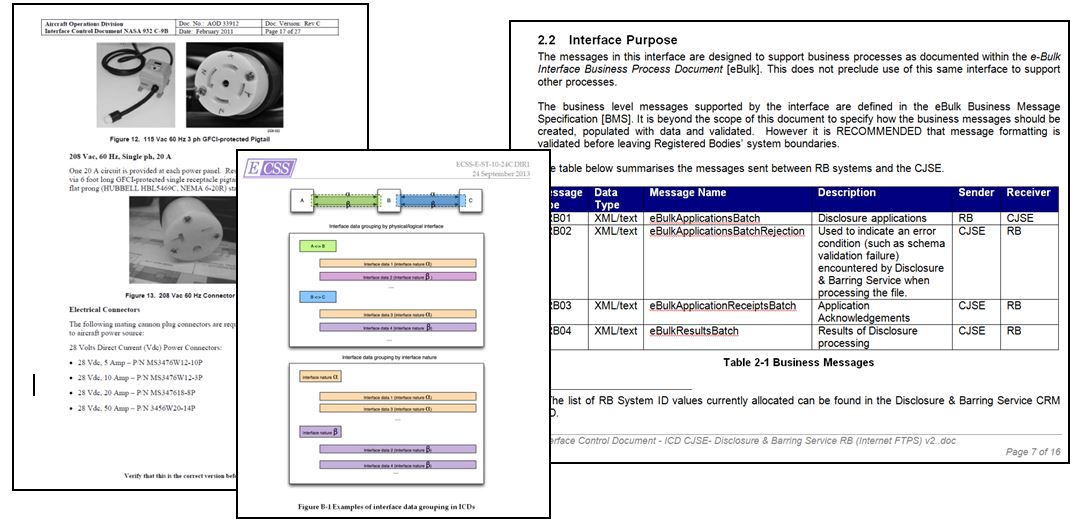
Fig 1. Styles of ICD documents
How SysML and modeling tools will help supporting ICDs?
- SysML Block Definition Diagram (BDD) and Internal Block Definition (IBD) with defined ports are quite equal to ICD.
- Currently there are no standards how to map ICD and SysML diagrams.
- Opportunity to introduce mapping rules or standards.
The next version (v18.3, 2016 January) of Cameo Systems Modeler will support the following ICDs.
Solution: Two predefined customizable ICD tables
Blackbox ICD Table.
A Blackbox ICD Table represents all external Ports and interfaces of the System (Block).
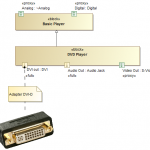
Case 1st Audio system
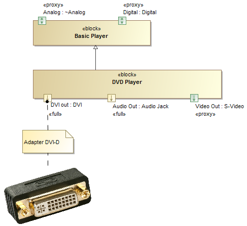
Fig 1. DVD player system
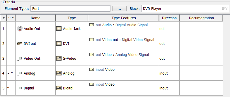
Fig 2. Single system ICD
Case 2nd Network cable
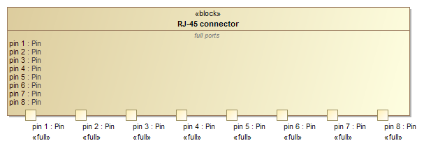
Fig 3. RJ-45 connector system
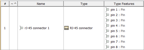
Fig 4. Single system ICD
Source: https://community.nomagic.com/modeling-ports-for-icd-automation-t2749.html
Whitebox ICD Table
A Whitebox ICD Table represents system assembly – how Parts are connected via Ports. Case 1st Audio system

Fig 5. Audio system
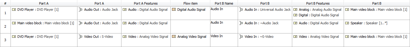
Fig 6. Subsystems ICD Table
Case 2nd Network cable
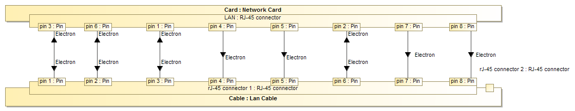
Fig 7. Network cable system
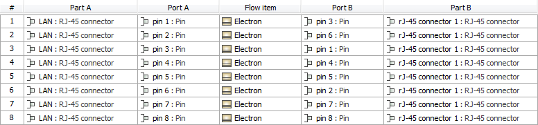
Fig 8. Subsystems ICD Table
Source: https://community.nomagic.com/modeling-ports-for-icd-automation-t2749.html
Conclusion
The views for system components interface are generated automatically from the system model. This provides up to date, efficiently managed, and fully featured model-based ICDs. The true model-based document-free approach is supported, along with all the capabilities of table export to document (images, html, .xls, .csv files).
ICDs table support is planned for the beginning of the next year, along with the v18.3 release. Check what’s new in Cameo Systems Modeler 18.3 FR.
References:
[1] “Training Manual for Elements of Interface Definition and Control”. Vincent R. Lalli, Robert E. Kastner,
and Henry N. Hartt, NASA Reference Publication 1370, January 1997.
[2] L.Sergent, T., L.Guennec, A.: Data-Based System Engineering: ICDs management with SysML,
ERTS2, (2014)
[3] Chambers & Associates Pty Ltd systems engineering glossary http://www.chambers.com.au/glossary/interface_control_document.php